


Introduction
Image stitching is the process of acquiring and merging a sequence of images into a single, large and detailed image. Microscope image stitching is widely used in biomedical research and material science to generate high-magnification images of sample areas which are much larger than the field of view (FOV). A wide FOV increases the probability of capturing rare and interesting events, while a high magnification supports building a detailed understanding of those events.

The microscopy image stitching process consists of two main steps: acquiring the images and combining them. During image acquisition, the camera is moved across the area to be captured and a sequence of images are captured in a pre-defined pattern. Combining these images is done in software.
Zaber’s motorized XY microscope stages make image stitching easy by enabling rapid and accurate automated image capture. This article will walk through the image stitching process using a Zaber microscope stage and the popular third-party microscopy software tool µManager.
Equipment
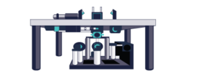
In this example, we will use modules from the Nucleus™ automated microscopy platform which provides a complete set of interchangeable hardware modules and software tools for building your bespoke inverted or upright standalone microscope or optical subsystem. Other microscope cameras have a similar performance. Try our online configuration tools guide you to choose microscope parts, automatically add any addition parts, and provide pricing at each step. You also contact Zaber if you are interested in configuring a system for your application.
Hardware:
- Zaber MVR Microscope – Automated inverted microscope with motorized XY movement, focus, and filter cube changes and integrated 3 channel LED illumination. Or
- X-ASR – Cost effective two-axis XY microscope stages with integrated controller and optional KX14B accessory kit with power and USB connection. Or
- X-ADR – High-speed and ultra-high repeatability linear motor XY microscope stage with integrated controller and optional KX14B accessory kit with power and USB connection.
Software:
- µManager – An open-source microscopy application developed and maintained by Open Imaging which provides a common control interface for a wide range of instruments.
- Fiji – An open-source image analysis platform.
Set-up
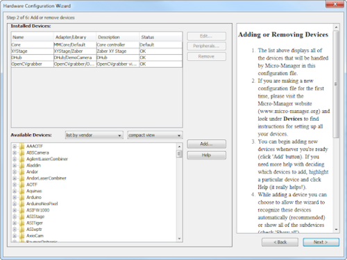
To configure the stage and controller, you must first install µManager, add the hardware, and follow the set-up instructions here. The X-ASR microscope stage should be set up as a two-axis XYStage device in µManager.
While adding the XYStage device in the Hardware Configuration Wizard, look for the OpenCVgrabber device in the Available Devices list and add it as well. OpenCVgrabber uses the open-source OpenCV library of computer vision drivers which supports most USB cameras, including the models from Dino-Lite. The list of installed devices should be similar to Figure 1.
After successfully configuring the hardware, an image from the microscope should be visible in the ImageJ window.
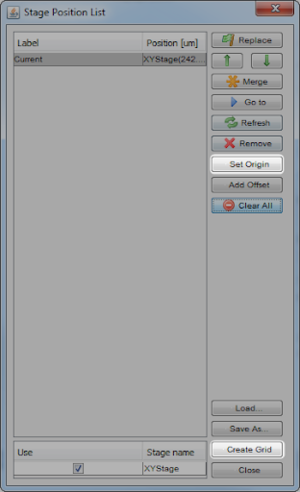
Next, set the origin of the microscope stage by selecting Tools > Stage Position List > Set Origin. This moves the stage to the ‘home’ and ‘away’ limit sensors which establishes a reference for positioning, as well as defining the usable travel range. Figure 2 highlights the Set Origin button and the Create Grid button for the next step.
Finally, calibrate the movement of the stage to the microscope field of view by setting the pixel size. Position the stage near the center, and focus on an area with sharp, clear details.
Select Devices > Pixel Size Calibration to add a new entry. Give the profile name which matches the objective you are currently using. Select the camera model name under the properties tab to associate it with the calibration data. Click Measure, then select Automatic and set the Safe travel radius to 10000 µm. Click Start. Save the calibration settings when the process is complete.
Repeat this process by creating a new entry in Pixel Size Calibration whenever a different magnification of the microscope is needed.
Capture an Image Array
Now that the devices are configured and calibrated, µManager can automatically capture the required images in sequential order. To create the grid of source images, select Tools > Multi-Dimensional Acquisition. In the window, check the Multiple Position (XY) box and select Edit position list…. Select Create Grid to open the Tile Creator.
The µManager Tile Creator tool will automatically determine the number and position of images required to cover the sample area.
Select the Hand tool:

and align the top left corner of the Snap/Live view with the top left corner of the region you want to capture. In the Tile Creator, there will be four Set buttons as shown in Figure 3. Select the top Set button and then the left Set button. Drag the Snap/Live view to show bottom right corner to be captured and press the right and bottom Set buttons.
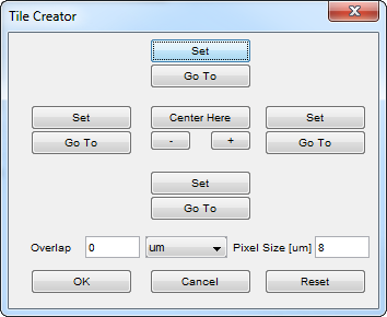
The Tile Creator allows you to specify a desired overlap. 15% is a good starting value which ensures that no details on the edges of images are missed, and allows smooth blending between images. Increasing the overlap value can be useful if you are using a lens which has optical distortion or decreased brightness away from the center of the lens. Depending on the pixel size and overlap values that are set, the original positions (top, right, left, bottom) may be shifted slightly to fit the grid calculated within µManager.
When you are finished, choose OK in the Tile Creator window and Close in the Stage Position List window. If you’d like to save all of the images, check Save Images and choose a directory to save them in. Finally, when you are ready to capture the images, select Acquire and the stage will start moving to each position in the grid while capturing images.
Stitch Images
Download Fiji from the link in the Equipment section above, you can open it by running the included executable file. Go to Plugins > Stitching > Grid/Collection Stitching.
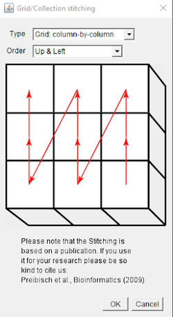
Select Type: Column-by-column, Order: Up & Left. Fill in the grid size, tile overlap, image directory, and file name information. The optimal settings for tile overlap can be determined by using the same pixel size and overlap settings that were used when creating the grid.
The individual image files will be loaded by FIJI sequentially based on their file names. Images saved by µManager use a different naming convention than is expected by FIJI. Rename the images using naming convention tile_{ii}.tif where {ii} is incremented, starting at {01}. Click OK to start stitching. The stitched image will be displayed once the process is complete.
Example Output
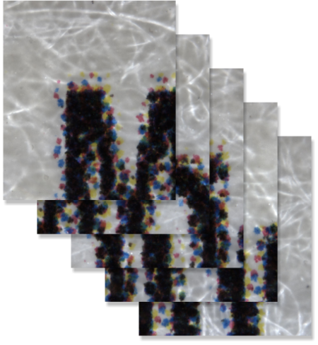
As an example, we captured an array of high-resolution images of the Zaber logo on one of our business cards as shown in Figure 5.

When the grid was created, it required 2 rows of 13 images to cover the area. A sample of the acquired images are shown in Figure 6.
Finally, Figure 7 shows the high-resolution assembled image from the Fiji stitching plugin.

Please email [email protected] or call +44 (0) 1933 461 666 to speak with one of our experts if you are interested in a custom system.