A
Amplitude Stability
The amplitude stability or output power stability defines the variation of laser amplitude or output power over time. The time period over which this stability applies is usually defined. The total amplitude stability of a laser can have several components: noise from drive electronics, other lab electronics, or competing optical modes beating against each other; thermal effects where changes in the temperature of the laser or the environment cause a variation in the electro-optical efficiency of the laser or drive electronics; and drift where the mechanical alignment of the laser cavity changes with time.
B
Bandwidth
Frequency bandwidth The frequency bandwidth is the rate at which a system may operate within specification when operating in a pulsed or modulated mode. The frequency bandwidth is normally defined as the 3dB bandwidth, the point at which the performance decreases by a factor of 3dB (50%). Optical bandwidth or laser linewidth The optical bandwidth (laser linewidth) is the range of optical wavelengths over which laser emission occurs simultaneously. Even a highly monochromatic laser source produces a range of wavelengths over which it emits simultaneously.
Beam Diameter
There are two definitions of beam diameter, the FWHM beam diameter and the 1/e2 beam diameter. The 1/e2 Beam diameter of a laser beam is the diameter of a spot centred on the laser beam that contains 87.5% of the total output power of that laser. This beam diameter is commonly applied to lasers with uniformly circular Gaussian beams such as DPSS and Gas lasers. The FWHM beam diameter of a laser beam is the diameter of a spot centred on the laser beam that contains 50% of the total output power of that laser. This is generally applied to laser diodes, where the emission profile of the laser is not circular.
Beam Dimensions
The beam dimensions define the cross-sectional size of the beam, to be used alongside the beam shape. To define the edge of the beam, two modes may be used, FWHM and 1/e2.
Beam Divergence
Beam divergence relates to the rate at which a laser beam expands with distance from the emission aperture. It is usually defined in the far-field (i.e. beyond the beam waist). A beam is said to be collimated where the divergence is low, and the beam radius remains approximately constant. Beam divergence is given in degrees or milliradians and is specified as: either the full angle of the cone of the beam divergence from the laser (“full angle”); or the half angle of the cone of beam divergence (“half angle”) from the laser.
Beam Parameter Product
The beam parameter product (BPP) is the product of a laser beam’s divergence angle (half-angle) and the radius of the beam at its narrowest point (the beam waist). The BPP quantifies the quality of a laser beam, and how well it can be focused to a small spot. A Gaussian beam has the lowest possible BPP, λ / π, where λ is the wavelength. The ratio of the BPP of an actual beam to that of an ideal Gaussian beam at the same wavelength is denoted M2 (“M squared”). This parameter is a wavelength-independent measure of beam quality.
Beam Pointing Stability
The beam pointing stability is a measure of the variation in the direction of a laser output beam, relative to a fixed point in an optical system.
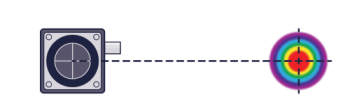
Beam Profile
Profiling measures the spatial characteristics of a laser beam such as intensity distribution, diameter, divergence, and M squared. It is achieved by taking a section through a laser beam and building a spatial map of the energy distribution. This is often presented as a 3d Cartesian with X & Y as the orthogonal spatial axes across the beam and with the third assigned to intensity. By revealing the whole optical intensity profile, exact, accurate numerical values can be assigned to the physical properties of the beam. Knowing the intensity profile of a laser beam is important for many applications.
Beam Quality
Beam quality is defined as a measure of the ability to focus a laser beam down to its theoretical minimum spot size. This can be quantified using the M2 factor.
Beam Shape
This is the shape of the spatial profile of the laser beam. It can affect how well the laser will work in a given application e.g : how the laser may be affected by different apertures; how well the laser may be focussed; which optics to use (spherical or cylindrical); and the maximum power density that can be achieved at the workspace.
Birefringence
A birefringent material has a refractive index that is dependent on the polarisation direction of the light that propagates through it. An optical beam passing through a birefringent material will generally be split into two components, an ordinary ray and an extraordinary ray, each of which has an orthogonal polarisation to the other. The axes of a birefringent material are classified “fast” where the refractive index is the lowest, with the slow axis referring to the orthogonal axis.
C
Cavity Type
DBR (Distributed Bragg reflector cavity) The distributed Bragg reflector cavity is a form of laser diode cavity that creates optical feedback which reduces the linewidth of the laser emission and the number of longitudinal modes that are present. It is similar to the DFB cavity but achieves higher wavelength coupling and offers the potential for much narrower linewidth generation. The narrow linewidth makes them suitable for spectroscopy and remote sensing applications.
Some DBR laser diodes are wavelength tunable by drive current. DBR lasers tend to exhibit higher wavelength stability than DFB and FP lasers when operated across their full operating temperature range. This makes them useful for multiplexed optical communications. Some generations of DBR laser diodes deliver long coherence length. Such lasers are suitable for use in applications such as holography, interferometry and sensing. DFB (Distributed feedback cavity) The distributed feedback cavity is a form of laser diode cavity that includes a specific region within the laser that creates optical feedback. This has the effect of increasing the optical amplification at a given wavelength, and consequently reduces the linewidth of the laser emission, and the number of longitudinal modes that are present.
The narrow linewidth makes them suitable for spectroscopy and remote sensing applications. Most DFB laser diodes are wavelength tunable by temperature and drive current variation. However they exhibit much higher wavelength stability across their operating temperature range. This makes them useful for multiplexed optical communications. Some generations of DFB laser diodes deliver long coherence length. Such lasers are suitable for use in applications such as holography, interferometry and sensing. Fabry Perot Cavity The Fabry Perot cavity is the simplest form of optical resonance cavity, based around two parallel plane reflectors. Light may only oscillate between the plane mirrors of the cavity if the modal wavelength conditions are fulfilled. Light of wavelengths that do not fulfil these conditions is emitted from the cavity. As a result the cavity acts as an optical filter.
Changing the mirror separation changes the wavelength response of the filter (or Etalon). The performance of the cavity is principally defined by the reflectivity of the mirrors. When used as a laser cavity, a Fabry Perot cavity tends to deliver relatively broad linewidth when compared to other cavities, and multiple longitudinal modes. Littman-Metcalf Configuration In an external cavity using the Littman-Metcalf configuration, the end mirror is also a diffraction grating, but it remains fixed at near grazing incidence. Instead, an additional mirror adjusts to tune the wavelength and to reflect the first-order diffracted beam back to the laser gain medium. This configuration tends to have lower output power than Littrow, as the zero-order reflection from the tuning mirror is lost. However, it can provide narrower line widths and broader tuning range. As the wavelength dependent diffraction occurs twice per round trip in the resonator, stronger wavelength selection results. Littrow Configuration
The Littrow configuration of an external cavity features a diffraction grating as an external cavity end mirror. The emitted wavelength is tuned by adjusting the angle and position of the grating. The first-order diffracted beam is reflected back to the laser gain medium, giving optical feedback. This configuration allows independent control of the output power and the wavelength-dependent feedback from the external cavity. Monolithic Cavity A monolithic cavity is a laser cavity constructed from a single element, achieving greater alignment stability. This can reduce the effects of thermal drift, mechanical vibration and long term component reliability issues.
MOPA Configuration MOPA stands for Master Oscillator Power Amplifier. A MOPA configuration combines a seed laser with an optical amplifier to boost output power whilst retaining many of the characteristics of the seed laser (such as the spatial mode, temporal mode, and coherence). Tapered Amplifier A tapered amplifier is a semiconductor optical device designed to amplify the signal of a low quality semiconductor source and to improve the resulting beam quality. The angle of the taper, and the length of the unamplified region are optimised to deliver high quality beams with low ASE noise.
Chirp
A chirped pulse is a pulse in which the frequency changes with time. A frequency increase is known as ‘up-chirp’, decrease as ‘down-chirp’.
Coherence Length
The coherence length is the distance over which the phase of the beam remains constant. It is the path length corresponding to the coherence time – the time over which coherence is lost. Multiplication of the coherence time by the vacuum velocity of light gives the coherence length. Alternatively, coherence length can be calculated by dividing the laser wavelength squared by the laser linewidth. Many applications require a long and stable coherence length such as holography and interferometry. However, long coherence length can lead to speckle and non-linear affects such as Brillouin scattering, which may be undesirable.
Collimation
A collimated beam has low divergence and a beam radius that is approximately constant. As all optical systems suffer from optical divergence, collimation can only be used to optimise the beam over a short distance.
D
D* (Detector Responsivity)
Detectivity is a key figure of merit used for photodetectors. It is proportional to the inverse of the smallest signal that can be detected. Hence a larger D* indicates a more sensitive detector.
Dispersion
Is defined as the dependence of the phase velocity in a medium on the optical wavelength, the mode of propagation, or the polarisation. Chromatic dispersion is where the phase velocity depends on the optical wavelength. It is caused by a frequency-dependent refractive index, or waveguide dispersion. It manifests itself as pulse broadening, where the duration of a pulse increases as the different wavelengths within the pulse travel at different speeds through the medium of propagation. Intermodal dispersion results from different propagation characteristics of higher-order transverse modes in waveguides, such as multimode fibres. Polarization mode dispersion results from polarization-dependent propagation characteristics.
E
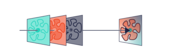
Edge Steepness
Edge steepness and transition width are two terms often used to describe the spectral properties of edge filters and it is important to know that these two terms are related, but not interchangeable. Edge Steepness is the actual distance between the place where OD>6 ends and the 50% transmission point. Transition Width is the maximum distance between the laser line (where OD>6) and the 50% transmission point. Transition width is the term most often used to specify filters in a catalog, as transition width allows the user to know exactly how far from the laser line he can expect to transmit light. Edge steepness is a more effective term to describe how fast the filter transitions from blocking to transmission. Please note that transition width is always greater than edge steepness.
Efficiency
Quantum Efficiency The quantum efficiency of a photo-detector or camera is defined as the number of photon collisions that are required to produce and electron-hole pair, and relates to the overall sensitivity of the detection system. Slope Efficiency (Differential Efficiency) Slope efficiency of a laser is defined as the ratio of laser output power versus the input pump power. As this value is generally linear for most lasers operating in the lasing region, it is sufficiently expressed as a single ratio. However, at conditions below laser threshold and close to peak output power, the variation of output power with input power becomes non-linear and this approximation is no longer accurate. Wall Plug Efficiency The total electrical to optical power efficiency of a laser system.
F
Fast Axis / Slow Axis
A birefringent material has a refractive index that is dependent on the polarisation direction of the light that propagates through it. An optical beam passing through a birefringent material will generally be split into two components, an ordinary ray and an extraordinary ray, each of which has an orthogonal polarisation to the other. The axes of a birefringent material are classified “fast” where the refractive index is the lowest, with the slow axis referring to the orthogonal axis.
Fibre Coupling
Fibre coupling is where the output power from a laser is coupled into the core of an optical fibre. Fibre coupling offers a number of advantages for example: remote location of the laser head from the work piece (e.g. surgery); combination of multiple wavelengths onto a single fibre (multiplexing in data and telecoms); improvement of beam quality (spatial filtering); and enclosing a large area (security and remote sensing). Most optical fibres have core diameters in the 5 to 500 micron range, depending on the spatial mode and the power handling requirements.
The method of alignment needs to be precise and stable to ensure that maximum coupling is achieved and remains constant in many different environments and over long periods of time. Many different forms of fibre coupled laser are available ranging from pseudo-monolithic devices to uncoupled lasers with fibre accessories separated in space. Cladding Mode Free Fibre (CMF fibre) A cladding mode is an optical mode that propagates in the cladding of an optical fibre. This is an undesired effect as it: increases optical power loss; degrades output quality; increases optical system noise and instability; and in the worst case, causes damage to the components of an optical system.
Cladding mode free fibre suppresses these modes. FC/APC Connector This is an industry standard optical fibre connector. It allows for quick connection of a device to an optical system in a way that is highly repeatable, stable and easy. APC “Angled Physical Contact” connectors are angle-polished. This prevents back-reflection into the optical system which can cause noise and instability. Large Core Fibre Coupling Large Core fibre coupling is a form of multimode fibre coupling, but is generally applied to fibres with cores greater than 100 microns. This form of fibre coupling allows numerous spatial modes and temporal modes of the laser beam to co-propagate. It is particularly useful for materials processing applications where large powers are to be handled within the fibre.
Fibres can be aggregated together to form bundles, with each fibre providing a source of laser power. When compared with singlemode fibre coupling, beam quality and coherence are compromised, but much higher powers are achievable. Multimode Fibre Coupling (MM Fibre) Multimode fibre coupling allows numerous spatial modes and temporal modes of the laser beam to co-propagate through the fibre. It is particularly useful for short reach and low data rate optical communications, and low power beam delivery systems for applications such as sensing and optical pumping.
When compared with singlemode fibre coupling, beam quality and coherence are compromised, but higher powers are achievable. Multimode fibres are available with core diameters of 50microns, 62.5 microns, 100 microns and greater. Polarisation Preserving Fibre coupling / Polarisation Maintaining Fibre Coupling (PM Fibre) Polarisation preserving fibre coupling is a form of singlemode fibre coupling. It uses a special type of fibre where the structure of the fibre core is designed to ensure that a single linear polarisation state is propagated along the length of the fibre.
Singlemode Fibre Coupling (SM Fibre) Singlemode fibre coupling preserves the spatial mode and temporal mode of the laser beam by allowing only one (single) mode to propagate through the fibre. However, it does not preserve the polarisation state of the fibre, which is randomised. It can be used to convert multi-spatial mode beams into single-spatial mode beams at the expense of increased loss. It is particularly useful for optical communications, distributed sensors, and applications where excellent beam quality or coherence is required. Singlemode fibres tend to have the smallest dimensions, with core diameters typically less than 10 microns.
Free Spectral Range (FSR)
The Free spectral range (FSR) is the spacing in optical frequency or wavelength between two successive reflected or transmitted optical intensity maxima or minima of an interferometer or diffractive optical element.
G
Group Delay
The group delay is a measure of the time delay incurred by a single pulse containing a group of wavelengths or polarisations as they propagate through an optical medium. The entire group will be retarded as it propagates through an optically dense medium. The amount of delay is defined as the group delay. Some wavelengths or polarisations within the group are delayed more than others. This leads to “pulse broadening” (an increase of the pulse duration). The rate at which slower signals are slowed in relation to the fastest in the group is termed the differential group delay.
H
High Brightness
The brightness of a laser beam is the ratio of the output power to the surface area of the laser beam. ‘High brightness’ refers to a laser having a large output power over a small active area and is particularly useful for increasing the SNR in optical imaging and the speed of material processing.
I
J
K
L
Laser Threshold
This is condition in a laser resonator above which laser emission commences. It is the point at which the small-signal gain within the laser resonator is equal to the resonator losses. High power output, power efficiency, beam quality, and stable low-noise performance require operation well above the threshold.
Laser Type
Amplified Spontaneous Emission Source (ASE) ASE sources have very low coherence, corresponding to the large emission bandwidth. They contain a laser gain medium that is excited to emit and then amplify luminescent light. They are alternatively known as superluminescent sources. Their properties make them useful in applications such as fluorescence excitation, and spectroscopy. DPSS Laser Diode-pumped solid state (DPSS) lasers use laser diodes rather than flash or arc lamps for optically pumping solid-state laser cavities. Although lamps are low cost and can provide high powers, they also give lower lifetimes, low power efficiencies and introduce unwanted thermal effects.
In comparison, DPSS lasers have a compact footprint and deliver efficient power consumption. They also offer potentially long lifetimes, low noise and high beam quality. Excimer Laser An excimer laser uses a gas mixture as the gain medium. This is typically a combination of a noble gas and a reactive gas. Pumped with a high voltage electric discharge in short pulses, the gases create excimers, pseudo molecules that only exist in an energized state. These usually emit laser light in the UV region.
External Cavity Diode Laser External cavity diode lasers combine a laser diode with external optics that extend the resonant cavity beyond the laser diode. By extending the cavity, the laser linewidth is narrowed, phase noise is reduced and the wavelength can be adjusted. Fibre Laser A fibre laser is a solid-state laser and is based around an optically pumped doped optical fibre. As the gain media has a large gain bandwidth, wide wavelength tuning ranges and ultrashort pulses are achievable. The high gain efficiency allows operation with small pump powers, giving high power efficiencies and contributes to their small size and power consumption. Their high output power, without amplifiers, eliminates spontaneously induced noise. This is particularly useful in sensing applications. Furthermore, the potential for long cavity length produces very narrow linewidth and high coherence with low phase noise. This is particularly useful for high-resolution interferometry. Single mode fibres give diffraction limited beam quality making them ideally suited to high performance material processing applications.
High output power and compact size are the trademarks of fibre lasers. As fibre laser construction is inherently more robust than other laser types, it lends itself to industrial and portable applications. Gas Laser These lasers use an electrically pumped gas mixture as the gain medium. Examples include lasers such as Helium-Neon, Argon Ion, Krypton ion that deliver outputs in the visible; Carbon Dioxide delivers outputs in the Infrared; and Nitrogen and a range of Excimer lasers output in the UV. Gas lasers have largely been replaced by the newer diode, DPSS and fibre laser technologies. However, they are still the only solution for very specific wavelengths. Laser Diode A laser diode uses electrically pumped semiconductor gain medium. Laser diodes are highly sensitive light sources.
The Laser 2000 range of laser diode current controllers, laser diode temperature controllers and laser diode mounts allow the output power, wavelength and mode stability to be adjusted with high precision, resolution and stability. This enables sensitive control and measurement. LED Light Emitting Diode A light emitting diode is a semiconductor device that emits light through electroluminescence. LEDs emit low powers in the UV, visible and infrared parts of the spectrum. They are broadband sources that are suitable for applications such as illumination, fluorescence excitation, sensing and spectroscopy. They are also used in low data rate optical communications. Quantum Cascade Laser / External Cavity Quantum Cascade Laser A Quantum Cascade Laser (QCL) is a semiconductor laser that emits highly coherent radiation in the mid- to long-wave infrared region of the spectrum.
QCLs are not diode lasers, but rather unipolar semiconductor devices consisting of hundreds of epitaxial grown layers forming a large number of quantum wells in the conduction band of the device. These are engineered to enable a cascade of photons emitted for each injected electron. QCLs generate light in the 4µm to 25µm region of the electromagnetic spectrum.
An External Cavity Quantum Cascade Laser (ECqcL™) is a semiconductor laser source. It integrates quantum cascade gain media into an external cavity having wavelength dependent feedback. ECqcLs™ are available either as precision fixed-wavelength sources, or as broadly tunable lasers. A tunable ECqcL™ can tune across the entire gain profile of the QC chip, allowing for tunability of 10% to 25% of the center wavelength. Solid State Laser Solid state lasers are based around a solid gain media such as ion-doped crystals or glasses, (e.g. Nd:YAG, Nd:YLF, Ti:sapphire, Nd:YVO4 etc…). These lasers have the ability to deliver highly coherent radiation in the UV, visible or Infrared ranges of the spectrum, in pulsed or CW forms and with high optical output power and quality. They also offer the ability to operate in highly singlemode states for applications requiring long and stable coherence. High powers can also be achieved, making them suitable for some materials processing applications.
Superluminescent Light Emitting Diode (SLED) SLEDs are semiconductor devices that incorporate high-power gain sections to give amplified spontaneous emission. Similar in construction to laser diodes, but without optical feedback to cause laser action, they combine the high power and brightness of laser diodes with the low coherence of conventional light-emitting diodes.
Linewidth
As laser light is a narrow band of wavelengths rather than a single wavelength, a lasers linewidth is the full width at half maximum of its optical spectrum. This is measured in wavelength, wavenumbers or frequency. Narrow linewidths are required for various applications. Used in spectroscopy, narrow linewidths give high resolution to allow adjacent absorption lines to be resolved. However, for some applications a narrow linewidth is not suitable. For advice on your particular application, please contact us – we will be happy to help you.
M
M² (M-Squared)
M², or beam quality factor, is a dimensionless parameter that characterizes the degree of imperfection of a laser beam. The closer the value is to 1.0, the closer the beam is to a perfect Gaussian beam and the closer it can be focused to its diffraction limited spot size. Due to the limitations of the optical cavity, the lasing medium and optics, most beams are not the ‘perfect’, diffraction-limited, Gaussian profile, pure TEM00 mode described in textbooks. Complex beams can contain multiple TEMnm contributions, leading to high values of M². At its simplest, M² can be defined as the ratio of the divergence of the actual beam to that of a theoretical, diffraction limited TEM00 beam with the same waist diameter. M² = Θ/θ where Θ = The measured, far-field, full-angle divergence of the actual beam. θ = The theoretical far-field divergence of a ‘perfect’ TEM00 Gaussian beam which has the same waist diameter as the measured beam. θ = 2λ/πW0. W0 = the second moment (4σ) beam waist diameter. The shape of the M² curve may be shown to be hyperbolic of the form: 2W(z) = 2W0√1+(z/ZR)². ZR is the Rayleigh Range, the distance at which the beam diameter is √2 greater than the diameter at the waist. This can be shown to be: ZR = 2W0/Θ = πW0²2/M²λ . The above equation provides a definition of M² in terms of a measured diameter: M² = (π/4λ)Θ2W0. ISO Standard 11146 relates to this measure.
Mode Hop
A mode hop is sudden change in the frequency output of the laser due to a switch of power from one resonator mode to another. The mode hopping of a laser wavelength when tuning can cause the optical output power to miss certain wavelengths between modes. In spectrometry, this can cause missing features in absorption profiles.
Mode Locked, Mode Locking
Mode locking is where a fixed phase relationship between the modes of the resonant cavity arises. This relationship can then produce optical interference within the cavity, with the resulting laser emission occurring as a train of high energy pulses. Mode locking is used to produce pulsed outputs with picosecond or femtosecond durations.
Modulation
Analogue Modulation Analogue modulation enables the user to control the intensity of the output power. An external voltage signal, typically in the range of 0-5V, determines the laser output. The response of the laser power output to the input voltage is approximately linear. Digital Modulation (TTL Modulation) Digital modulation enables the user to modulate the output power of the laser diode digitally between zero power and maximum power via an external 5V TTL input. Available as a standard or optional feature on most of our lasers, this can also be used to switch the laser on or off remotely. The modulation frequency, Hz, refers to the speed at which the laser can be switched on and off. Pulse Picker A pulse picker is an electrically controlled optical switch that blocks all but a specific single pulse in a pulse train. Q-Switching Q switching is a technique for obtaining energetic short pulses. The intracavity gain is modulated using a variable attenuator such as a saturable absorber or acousto-optic modulator. The technique generates nanosecond pulses of high energy and peak power.
Monolithic
Monolithic meaning “consisting of one piece” is typically applied to complex multiple optical elements that are provided as single elements. Monolithic optics offer a number of advantages over traditional air-spaced multiple optical element assemblies. They deliver greater stability and more resistance to drift of alignment, and provide greater resilience to shock and acceleration. Furthermore, they tend to be more compact, opening up opportunities for applications denied to larger multi-element systems.
N
Noise
Optical noise manifests itself as variations mostly in the phase and amplitude of a laser. Generally unwanted, it can have several causes, some of which are easier to remove than others. All laser outputs exhibit some noise of varying degrees: Optical noise has many different sources: quantum noise from spontaneous emission in the gain medium; noisy drive electronics; interference from external EM sources; optical feedback; and environmental factors such as shock, vibration, and temperature fluctuations. Lasers operating on multiple resonator modes exhibit mode beating noise and mode partition noise, where the power distribution over the resonator modes fluctuates. Noise can also appear in the timing of the pulses (jitter), in the centre wavelength, the pulse duration, and frequency chirp. Phase & frequency noise cause laser linewidth broadening and limit the coherence. Amplitude noise has many serious effects in optical systems. Its effects can be far reaching: reducing the SNR in remote sensing and spectroscopy; degrading image quality in microscopy; and causing bit errors in datacoms.
O
Optical Amplifier
An optical amplifier increases the power of an optical beam by use of an optical gain medium. The signal is amplified optically, and not converted into an electrical or electronic signal beforehand. This preserves many of the qualities of the laser.
Output Power
Average Output Power This is the total power emitted by a pulsed beam, averaged over one period. For a pulsed laser delivering peak power per pulse of Ppeak with a pulse width of Pw and pulse repetition frequency of f, the average output power, Pave, is defined as: Pave = Ppeak x Pw x f Peak Output Power The maximum power of a train of identical pulses. This can be calculated from the average power and duty cycle (the fraction of the time period during which the laser is emitting): Ppeak (P0 on graphic) = Pavg/Duty Cycle Assuming a square pulse, Ppeak = Pavg / (Pulse rate * pulse duration (width))
P
Package Type
Bar Array Several different versions of bar-array packages are available depending on the power and temporal characteristics of the laser emission. These mounts offer close packing and high density of the emitted laser radiation. They allow multiple arrays to be stacked together to produce many kW of integrated laser output for pumping or materials processing applications. Temperature control, and heat removal is important for these lasers to operate within specification and with long lifetimes. These mounts are designed to be used with a third party heatsink or temperature control (such as recirculating water, Peltier effect TECs or forced air, or passive conduction).
Bench Top A bench top laser comprises a laser head and a freestanding power supply unit. The power supply unit (PSU) incorporates control electronics, matched to the laser head. A custom cable is provided to make the connection between the laser head and PSU. Extremely user friendly, this laser format is ready to use once plugged into a mains supply. Butterfly The butterfly package is an industry standard hermetically sealed laser diode package. The BFY package is comprised of laser welded gold plated Kovar. This has very similar expansion characteristics to the borosilicate glass used in the frit seals and optics to deliver the ultimate in robustness and reliability. The package is also provided with a fibre pigtail (either singlemode or polarisation preserving with an FC/PC or APC connector). Horizontal pins arranged symmetrically on both sides are provided for connection to a suitable laser diode & TEC controller. Several different pin-out configurations are provided as standard. Most options include: a Peltier effect TEC and thermistor for temperature measurement, control, and stabilisation; and a monitor photodiode for output power measurement, power control and mode hop free performance.
C-mount The C-mount is a format of open laser diode chip mount. It is designed to remove heat from the laser diode and be cooled actively by adequate heat-sinking to a 3rd party supplier cooler. OEM-component An OEM component is a package format defined specifically for a particular product. It may be standard between several suppliers, but may not be recognised as a standard across the entire industry. Rack Mount (19″) The 19″ rack mounting system is a space saving method of packing instrumentation into a highly compact tower. Each of the racks is 19″ wide and is stacked vertically in industry standard unit sizes of n x 1U height (where 1U = 1.75″(44.5mm)). Substrate In this case, the laser diode is mounted directly to a ceramic or metallic sub-mount without any other packaging. Connection is made by soldering flying leads to, or making wire bonds to the substrate.
TO Transistor Outline Hermetically sealed laser diode chip package. ‘TO’ stands for Transistor Outline. The number refers to the case style. For example TO-39 is a metal ‘can’ package for semiconductor devices, sealed to protect the device from moisture and contaminants.
Phase
The phase of a wave indicates the current position of the wave relative to a reference position. Phase is normally measured in degrees, where 360 degrees represents a single cycle of one wavelength. Two waves propagating with zero phase difference (0 degrees) are said to be in phase with each other and produce constructive interference. Similarly, waves propagating out of phase produce destructive interference, with maximum at 180 degrees phase difference.
Polarisation of Laser Emission
Laser polarisation refers to the direction of oscillation of the electric field. Many lasers produce polarised outputs, the gain or resonator losses may be polarisation dependent. Those that do not give a polarized output, such as many fibre lasers, do not necessarily have a truly unpolarised output. Rather than the two components having equal powers at any time, it may simply be an unstable polarisation state that is constantly changing at high frequency.
Polarisation Ratio
The measure of polarisation, ‘polarisation extinction ratio’ quantifies the degree of linear polarisation. It is the ratio of optical powers in the maximum and minimum axes of the elliptical representation of the beam profile. This is effectively the same as the ratio of the transmission of the unwanted component to the wanted component.
Pulse Compression / Pulse Expansion
Pulse compression reduces the pulse duration of an optical pulse. Various methods are used depending on the type of source. Most solutions use some form of grating or non-linear optical effect.
Pulse Duration (Pulse Width)
This is the duration of a single pulse of a pulsed laser, and is the time during which the pulse output power is above one half of its maximum value (typically). This is known as full duration at half maximum (FDHM).
Pulse Energy
The optical energy contained within a single laser pulse. It is often calculated by dividing the average output power (Pave), by the pulse repetition frequency (f, Hz) Epulse = Pave/f It is also possible to calculate from the peak power of a laser, provided that the peak power is expressed per pulse and has highly uniform over the pulse duration. Epulse = Ppeak x pulse duration
Pulse Repetition Frequency
Also known as the pulse repetition rate, this is the number of pulses emitted per period. When the period is 1 second, the pulse repetition frequency is given in Hertz.
Pumping
End Pumping Pump light is injected into the gain medium in the same axis as the propagation axis of the laser emission. Side Pumping Pump light is injected into the gain medium at an orthogonal axis to the propagation axis of the laser emission.
Q
R
Rayleigh Length
The Rayleigh Length is the distance from a beam waist at which the mode radius has increased by a factor of √2.
Resonator Modes, Transverse & Longitudinal
Modes of an optical or microwave cavity (resonator). Due to the effect of interference on light confined within a cavity, only certain spatial patterns and frequencies are sustained. Radiation patterns that reproduce themselves on each round trip through the resonator are the most stable and form the modes. Longitudinal modes differ in frequency, transverse modes in both frequency and intensity pattern. The fundamental transverse mode of a resonator, TEM00, is a Gaussian beam.
S
Seeding (Injection)
Injection seeding is a method used to force narrowband operation of a laser. The technique involves coupling light from a seed laser into the resonator of a slave laser. If the frequency of the seed light is close enough to the resonant frequency of one of the modes of the slave laser, that particular mode will oscillate in preference over the others and will extract much higher power than the competing modes. This mode will dominates the output, reduce the emission bandwidth, and give a smoother temporal pulse profile.
T
Temporal Mode
Continuous Wave, CW (Laser Output) CW lasers emit laser radiation constantly with time. The output power may be adjusted by the source or by the use of attenuators in the beam path, but emission continues until the laser is switched off or reaches the end of its lifetime. Pulsed (Laser Output) A pulsed laser emits light in the form of a single pulse or a train of optical pulses. A pulsed laser is defined by temporal characteristics such as the duration of each pulse (pulse width/pulse duration) and the rate at which pulses are repeated (pulse repetition frequency). Pulsed lasers may emit pulses that display do not exhibit uniform pulse rates, durations or energy. This is often described as jitter. QCW Operation (Quasi-Continuous Wave) A QCW laser emits a stream of pulses at a high frequency. The peak and average powers of the laser are of similar magnitudes and the laser behaviour approximates to that of a CW laser.
Timing Jitter
Is defined as the random variation of the repetition frequency of a pulsed laser.
Transition Width
Transition width and edge steepness are two terms often used to describe the spectral properties of edge filters and it is important to know that these two terms are related, but not interchangeable. Transition Width is the maximum distance between the laser line (where OD>6) and the 50% transmission point. Edge Steepness is the actual distance between the place where OD>6 ends and the 50% transmission point. Transition width is the term most often used to specify filters in a catalog, as transition width allows the user to know exactly how far from the laser line he can expect to transmit light. Edge steepness is a more effective term to describe how fast the filter transitions from blocking to transmission. Please note that transition width is always greater than edge steepness.
Tuning Wavelength Range
The wavelength of some lasers can be easily changed by the end user. This is usually achieved by adjusting the optics or electrical drive parameters (current and temperature) of the laser. Such lasers are referred to as tunable lasers. The tuning range is the maximum and minimum limits of the range of wavelengths over which the laser can be tuned.
U
V
W
Wavelength
Where ‘Wavelength’ is referenced in our lasers section, this refers to the centre wavelength of the beam.
X
Y
Z