


When selecting a high precision linear stage, positioning accuracy, backlash, and repeatability are typically the most important considerations. However, depending on the linear motion application, angular errors such as pitch, roll, yaw and Abbe errors can become critical. These angular errors can lead to significant displacements away from the stage top and unwanted or unexpected positional errors in the system.
Abbe errors, also called sine errors, are small linear displacements caused by angular errors at some distance from the stage top of a linear motion device. These angular errors can be caused by small structural imperfections in the linear bearings or mounting surfaces that a stage is fastened to, errors in the drive mechanism or feedback system from placement and alignment of the lead screw, ball screw, linear motor or encoder.
The Three Primary Errors
The diagram below illustrates the three angular errors for a single axis linear stage.
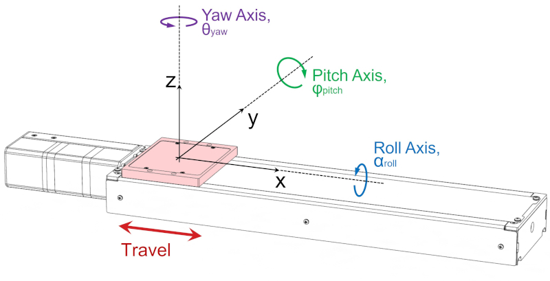
Rotation about these axes will cause positioning errors in 3D space if the point of interest is not located at the centre of rotation:
- Pitch rotation will cause an Abbe error in the xz-plane
- Roll rotation will cause an Abbe error in the yz-plane
- Yaw rotation will cause an Abbe error in the xy-plane
The diagram below shows Abbe error from rotation about the pitch axis, when the point of interest is coaxial with the Z or yaw axis. In this case the pitch error will affect the position of the point of interest parallel to the travel direction. Thus the Abbe error, δ, is directly additive to the device’s linear accuracy specification.
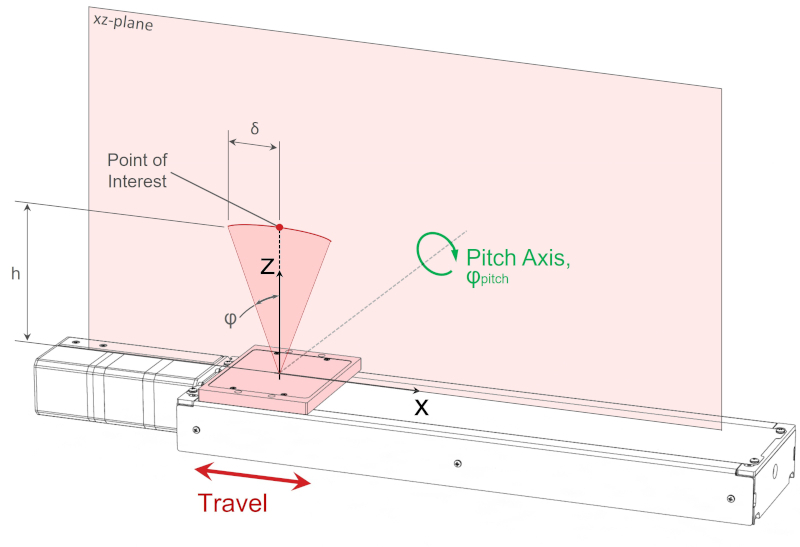
When the point of interest is coaxial with the yaw axis, the Abbe error from pitch axis rotation is defined as:
δ = h·tanφ
(1)
where,
- δ is linear displacement or error [mm]
- h is height above stage top or relevant distance from pitch rotation axis [mm]
- φ is pitch axis angular error [°]
The same principles can be applied to roll axis rotation (yz-plane) and yaw axis rotation (xy-plane).
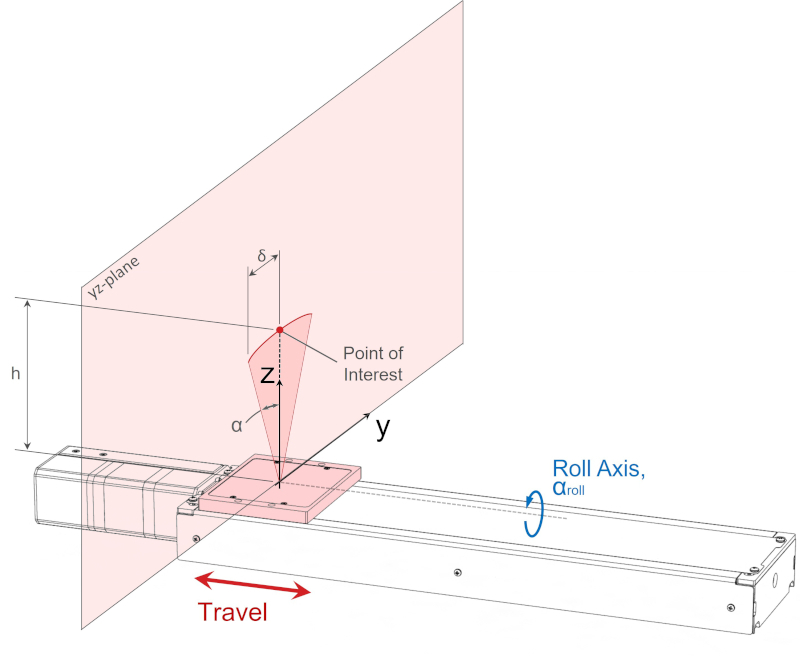
When the point of interest is coaxial with the yaw axis, the Abbe error from roll axis rotation is defined as
δ = h·tanα
(2)
where,
- α is roll axis angular error [°]
The majority of this error is parallel to the y-axis, and is directly additive with the device’s horizontal runout specification.
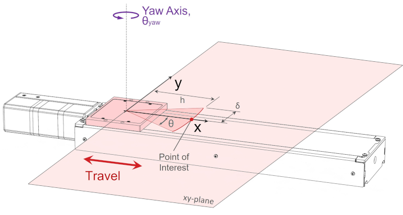
When the point of interest is coaxial with the roll axis, the Abbe error from yaw axis rotation is defined a
δ = h·tanθ
(3)
where,
- θ is yaw axis angular error [°]
Again, the majority of this error is parallel to the y-axis, and directly additive with the device’s horizontal runout specification.
The astute observer will note that there will also be a small “cosine error” in all 3 examples above. Revisiting the pitch error example, the cosine error will result in a small deviation in z-height, δz, as is illustrated below.
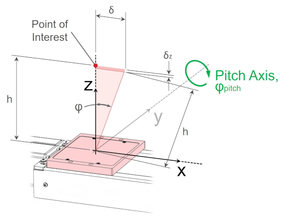
When the point of interest is coaxial with the yaw axis, the change in z-height from pitch axis rotation is
δz = h·(1 – cosφ)
(4)
where,
- δz is linear displacement or error along the z-axis [mm]
Cosine errors like this can generally be ignored, except in the case of extremely accurate instruments, since the magnitude of the error will usually be insignificant relative to other errors it adds to.
For ease of visualization, the examples above have dealt with simple cases where the point of interest is coaxial with one of the X, Y or Z rotation axes. However, that is rarely the case in practice. For an arbitrary point of interest, P, located at coordinates in 3D space:
P = (xp, yp, zp)
Where the distances are measured from the center of the stage top, there are 6 Abbe errors that may be worth considering:
δx, pitch = zp·tanφ
δx, yaw = yp·tanθ
δy, roll = zp·tanα
δy, yaw = xp·tanθ
δz, pitch = xp·tanφ
δz, roll = yp·tanα
These 6 errors won’t be shown graphically here, but will be used in all of the following examples to calculate Abbe errors in more complex multi-axis systems.
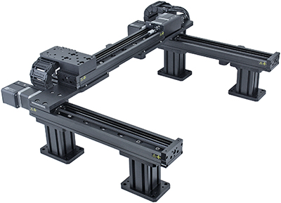
Example 1: Two Axis XZ System
To demonstrate a practical example, let’s consider an LRQ XZ system where two linear stages are mounted perpendicular to each other with an AB164 bracket. The bottom stage travels in the x-axis and the upper stage travels in the z-axis. This particular set-up is shown below.
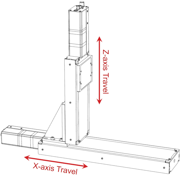
The vertical stage (z-axis) has 150 mm of travel, the horizontal stage (x-axis) has 300 mm of travel. The 300 mm LRQ linear stage has the following angular error specifications:
- Pitch: 0.034°
- Roll: 0.015°
- Yaw: 0.03°
For this XZ application, we determine the pitch and roll angular error to be the most important because of the potential large offset from the pitch axis and roll axis to the point of interest. The yaw rotation axis offset is smaller and constant in this configuration, therefore the yaw Abbe error is smaller than either the pitch or roll Abbe error, but is still worth calculating. The yaw axis offset could be reduced with a custom bracket, to bring the z-axis stage towards the centre of the x-axis stage top if desired.
Pitch error results in small displacements parallel to the x-axis of the vertical LRQ stage top. To quantify the impact of this error we need to know the physical locations of each stage top. Our point of interest is centred on the z-axis stage top, the worst case scenario is when the z-axis is at the top because the offset is the largest. The offset depends on the z-axis travel position. Referring to the 3D model and drawing we determine that the distance between the centre of the x-axis stage top and centre of the z-axis stage top is 212 mm. This important distance is shown below.
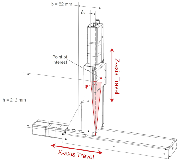
For the worst-case scenario, the pitch Abbe error is:
δx, pitch = h·tanφ = 212 mm x tan(0.034°) = 0.126 mm = 126 μm
For many applications, 126 μm is significant. The linear accuracy specification of an LRQ linear stage can be as good as 10um with a direct linear encoder. The resultant Abbe error is an order of magnitude larger than the travel accuracy of these direct encoder stages. To minimise the effect of Abbe error, the offset distance h, has to be minimised.
The change in z-height due to pitch axis rotation is:
δz, pitch = b·tanφ = 82 mm x tan(0.034°) = 0.049 mm = 49 μm
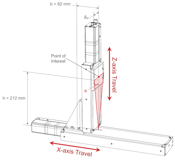
The rated roll error specification for the x-axis LRQ300 is 0.015°, for a point of interest 212 mm above the stage top, the Abbe error on the yz-plane parallel to the y-axis is:
δy1, roll = h·tanα = 212 mm x tan(0.015°) = 0.056 mm = 56 μm
The angular error along the y-axis from x-axis stage top roll rotation is shown in the diagram below.
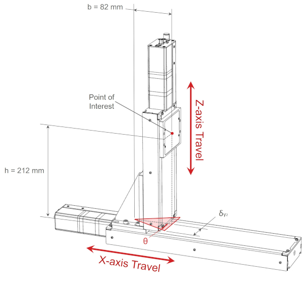
The rated yaw error specification for the x-axis LRQ300 is 0.03°, for a point of interest 82 mm from the centre of the x-axis stage top, the Abbe error on the xy-plane parallel to the y-axis is:
δy2, yaw = b·tanθ = 82 mm x tan(0.03°) = 0.043 mm = 43 μm
The angular error along the y-axis from x-axis stage top yaw rotation is shown in the diagram below.
Example 2: Two Axis XY System
For the XZ system in the last section, yaw error was the smallest error, as the z-axis stage top is closer to the yaw axis of rotation. Any Abbe error from yaw axis rotation would generally be insignificant. The yaw axis offset is constant and does not change depending on travel position. However, in XY configurations as shown below, yaw error is far more important.
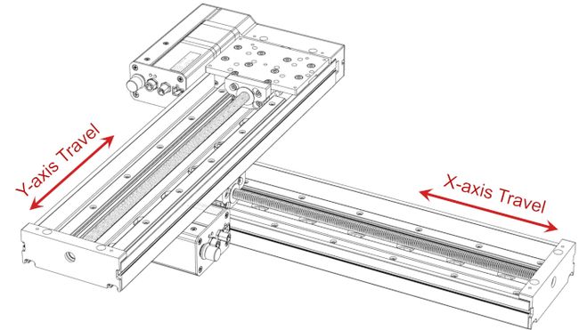
The motion for this XY system is shown in the animation below.
As the upper y-axis stage top moves to the end of travel, we can see there is a significant offset distance between the stage tops. Considering the direction of the offset tells us which angles will cause the most Abbe error. The distance from the pitch rotation axis is very small in this XY system, but there is significant offset from the roll and yaw axes. Therefore, we determine that roll and yaw axis rotation of the x-axis stage top will cause the most Abbe error. The magnitude of the Abbe error will be greatest when the y-axis is at the limits of travel, this is because the distance from the rotation axis is the largest at these two locations.
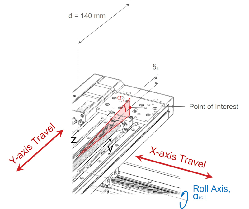
The yaw error specification for an LRQ300 linear stage is 0.03°. Referring to the 3D model and drawing, we determine that the centre of the upper y-axis stage top is 140 mm from the centre of the lower x-axis stage top.
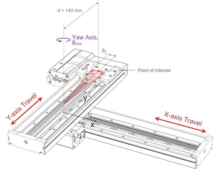
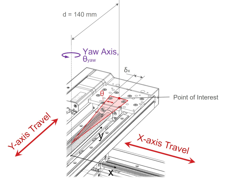
The Abbe error parallel to the x-axis from yaw axis rotation at the point of interest is:
δx, yaw = d·tanθ = 140 mm x tan(0.03°) = 0.073 mm = 73 μm
For this XY configuration, the mounting squareness of the stages is important too. This is generally called orthogonality error and the angle remains constant throughout the lower axis travel depending on the initial alignment, whereas, yaw Abbe error changes throughout the lower axis travel. Orthogonality error can be calculated using the same method as yaw Abbe error, but the angle is actually the misalignment of assembled XY stages. The additional linear error from orthogonality error can be added to the yaw Abbe error along the x-axis. With orthogonality error, y-axis travel results in position error along the x-axis.
We can use the same principles to determine the Abbe error from roll axis rotation. The point of interest remains 140 mm from the axis of rotation.
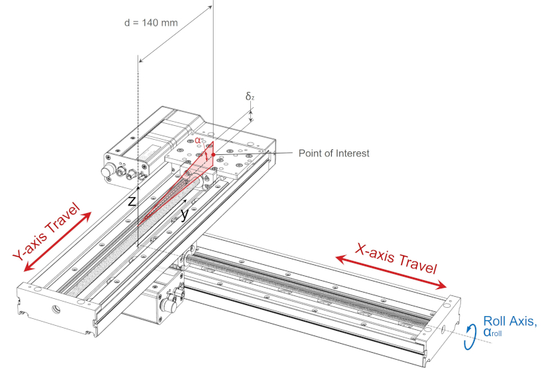
The roll error specification for an LRQ300 linear stage is 0.015°. The Abbe error parallel to the z-axis from roll axis rotation at the point of interest is:
δz, roll = d·tanα = 140 mm x tan(0.015°) = 0.0366 mm = 37 μm
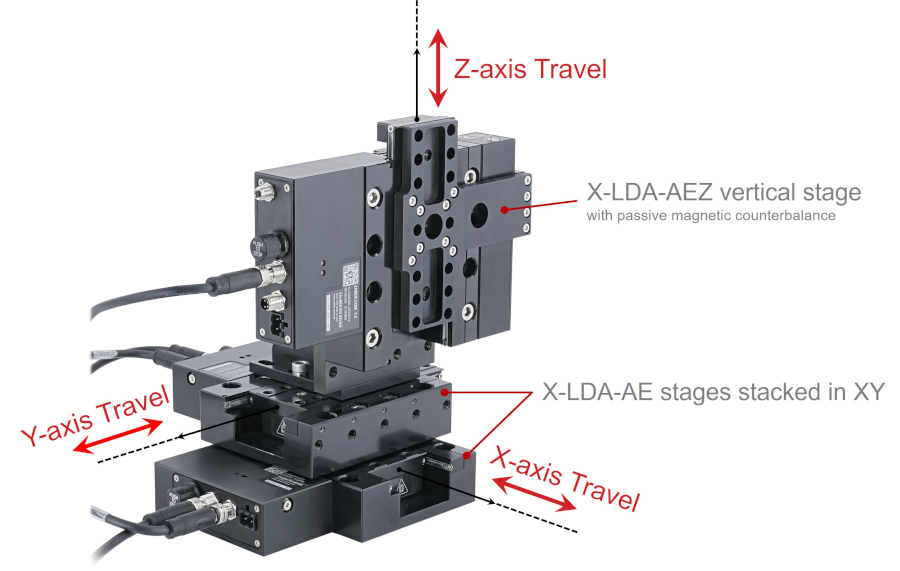
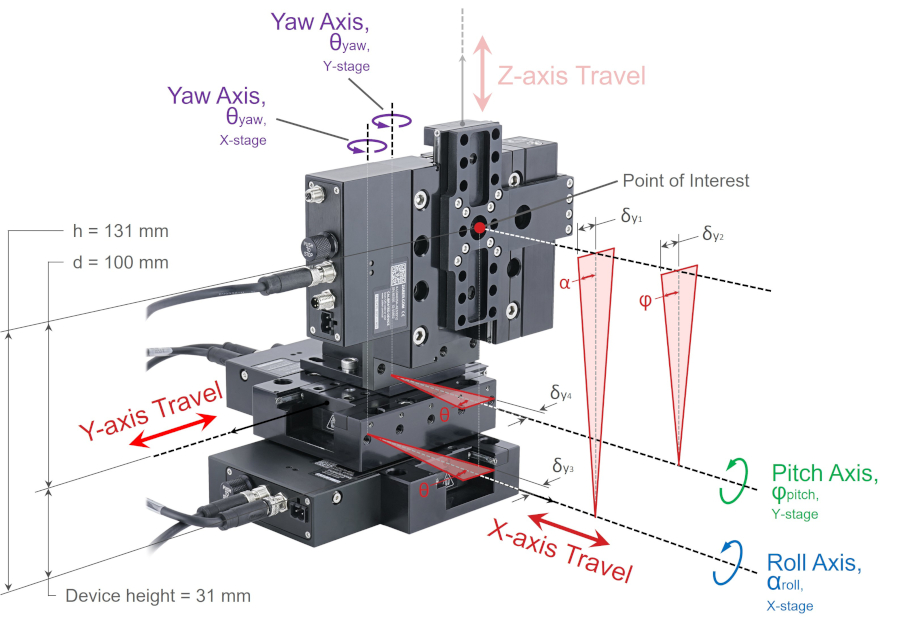
Example 3: Three Axis XYZ System
We can apply this procedure to more complicated XYZ stages and Gantry systems. Pitch, roll and yaw errors of the lower stages can accumulate in a cascading effect and result in larger displacements at the point of interest on the final linear stage in XYZ systems. The offset distance is usually larger in XYZ systems as the height and length of each linear stage is added.
The pitch, roll and yaw specifications for the LDA025 stages with 25 mm of travel are:
- Pitch: 0.006°
- Roll: 0.005°
- Yaw: 0.005°
Reviewing the device drawing we find that each LDA stage is 31 mm tall. The y-axis stage top is 31 mm above the x-axis stagetop. The z-axis is mounted vertically to the y-axis with a AB151 bracket. The centre of the z-axis stage top at our point of interest is 100 mm above the y-axis stage top and 131 mm above the x-axis stagetop.
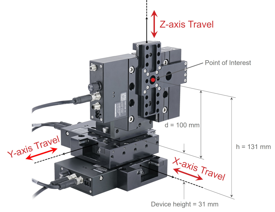
Abbe errors resulting from x-axis stage top pitch, roll and yaw angular errors are multiplied by h = 131 mm. Abbe errors resulting from y-axis stage top pitch, roll and yaw angular errors are multiplied by d = 100 mm.
Let’s examine the Abbe errors at the point of interest with respect to the xyz coordinate system. First we will consider Abbe errors that result in displacement of the point of interest parallel to the x-axis. There are three major components causing displacement along the x-axis. Abbe error along the x-axis at the point of interest on the z-axis stage top is illustrated below.
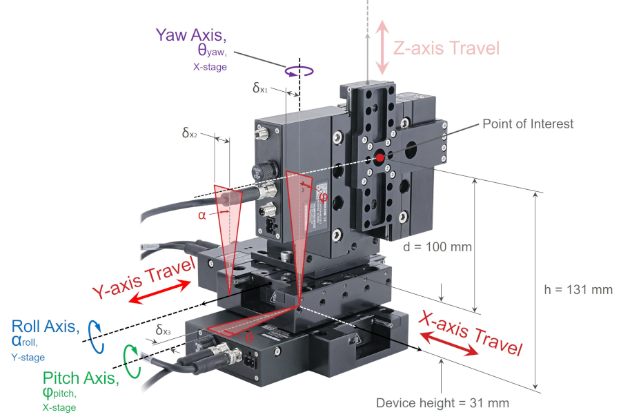
The major components contributing to displacement parallel to the x-axis are Abbe errors caused by:
- X-axis stage top:
- pitch axis rotation, which is shown by δx1 and angular rotation φ
- yaw axis rotation, which is shown by δx3 and angular rotation θ
- referencing figure 20b for yaw axis offset
- Y-axis stage top:
- roll axis rotation, which is shown by δx2 and angular rotation α
δx1, pitch = h·tanφ = 131 mm x tan(0.006°) = 0.0137 mm = 13.7 μm
δx2, roll = d·tanα = 100 mm x tan(0.005°) = 0.0087 mm = 8.7 μm
δx3, yaw = b·tanθ = 18 mm x tan(0.005°) = 0.0016 mm = 1.6 μm
The potential deviation in position along the x-axis at the point of interest would be the sum of these three errors, δx1, pitch + δx2, roll + δx3, yaw = 24 μm. However, this does not include any potential errors caused by vertical runout or horizontal runout of any of the stages. In certain cases, it may be necessary to include all the possible errors. To do this we would also need to add the following:
- Linear accuracy error of the x-axis stage, which is less than 1 μm
- Horizontal runout of the y-axis stage, which is less than 4 μm
- Vertical runout of the z-axis stage, is also less than 4 μm
Now consider Abbe errors that result in displacement of the point of interest parallel to the y-axis. There are four major components causing displacement along the y-axis. Abbe error along the y-axis at the point of interest on the z-axis stage top is illustrated below.
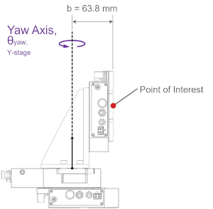
The Abbe error from yaw axis rotation of the lower axis stage tops is more easily visualised when looking at a side view and top view of the XYZ-LDA system shown below.
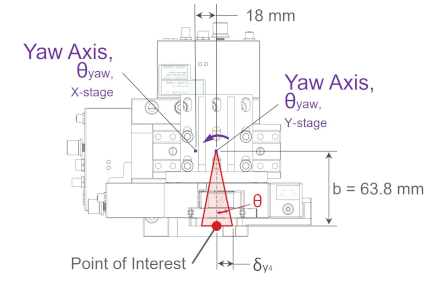
In figure 20b, the X-axis stage top yaw Abbe error is similar to the y-axis yaw error but is not shown in the diagram for clarity.
The major components contributing to displacement parallel to the y-axis are Abbe errors caused by:
- X-axis stage top:
- roll axis rotation, which is shown by δy1 and angular rotation α
- yaw axis rotation, which is shown by δy3 and angular rotation θ
- Y-axis stage top:
- pitch axis rotation, which is shown by δy2 and angular rotation φ
- yaw axis rotation, which is shown by δy4 and angular rotation θ
δy1, roll = h·tanα = 131 mm x tan(0.005°) = 0.0114 mm = 11.4 μm
δy2, pitch = d·tanφ = 100 mm x tan(0.006°) = 0.0105 mm = 10.5 μm
δy3, yaw = b·tanθ = 63.8 mm x tan(0.005°) = 0.0056 mm = 5.6 μm
δy4, yaw = b·tanθ = 63.8 mm x tan(0.005°) = 0.0056 mm = 5.6 μm
The potential deviation in position along the y-axis at the point of interest would be the sum of these four errors, δy1, roll + δy2, pitch + δy3, yaw + δy4, yaw = 33 μm. Again, this does not include any potential errors caused by vertical runout or horizontal runout of any of the stages. It may be necessary to include all the possible errors in some applications. To do this we would also need to add the following:
- Linear accuracy error of the y-axis stage, which is less than 1 μm
- Horizontal runout of the x-axis and z-axis stage, for a combined error of less than 8 μm
Additional Considerations
In practical applications, the probability of all of these angular errors occurring simultaneously at a specific location is low. These are the worst-case pitch, roll and yaw angular errors for a given linear stage. Angular errors typically occur gradually over the whole travel range, so there are usually no sudden changes or inflections in the errors when the stage top is moving. Typically the system accuracy in 3D space will be better than what was presented in this article. It is common engineering practice to use the square root of the sum of squares method, commonly referred to as Root Sum of Squares, for combining a series of dimensional tolerances together. The potential angular errors of each stage are independent and uncorrelated; we can make the assumption that not all tolerances will be at their worst at the same moment in time.
δy = sqrt (δy1² + δy2² + δy3² + δy4²)
(5)
δy = sqrt ((11.4)² + (10.5)² + (5.6)² + (5.6)²) = 17.4 μm
While the example above shows that the worst case error along the y-axis could be 33 um, this result tells us that we are more likely to observe an error of around 18 um, approximately 45% less.
In this article we neglected to consider the angular stiffness of each axis, and the possible deflections when loads and moments are applied to the stage top. The math is the same but you need to calculate the additional angular deflection based on the stiffness of each stage and moment arm of the payload with respect to each rotational axis. Zaber provides pitch stiffness, roll stiffness and yaw stiffness specification for each linear stage. The rotational stiffness equation, which obeys an angular form of Hooke’s Law, is shown below:
Ƙ = τ/ɸ
(6)
where,
- Ƙ is angular stiffness [N⋅m/°]
- τ is torque or moment [N⋅m]
- ɸ is angular deflection [°]
Rearranging the above equation to solve for the angular deflection is straight forward, ɸ = τ/Ƙ. The deflection for each axis of rotation needs to be considered individually, since the moment arm length and angular stiffness for each axis is different. In highly dynamic applications, the acceleration forces acting at the payload center of mass should also be considered.
After consideration, if the potential Abbe errors in your set-up are larger than you can tolerate, look for a linear stage with very small pitch, roll and yaw error specifications and with high angular stiffness. Zaber’s LDM Family offers our highest precision. For longer travel applications the LRT Family is a good choice. In more complex or multi-axis systems, there are some more in depth strategies that can be used to minimise Abbe error in your application:
- Consider using a second passive rail for the x-axis to eliminate roll error.
- With Zaber’s product customisation team it’s also possible to add a second passive carriage to a linear stage which will reduce pitch error and increase stiffness.
- Consider using a parallel drive configuration with lockstep to eliminate roll and yaw error.
- For pre-assembled versions of these systems you can use Zaber’s gantry configurator.