


If you’d like a free Pocket Polariser, just complete our contact form, with “Please send me my freePocket Polariser” in the message field.
Founded in 1979 by Tom Baur a pioneer in the field, awarded the SPIE G.G.Stokes award in 2018, Meadowlark optics are polarisation experts, providing polarisation components, liquid-crystal devices, spatial light modulators and polarisation instrumentation.
The following blog provides an overview of retarder (waveplate) principles, the different retarder types, materials used and how to practically use them in your experiments/products.
Written by our partners Meadowarlark Optics.
10-15min reading time.
A retarder (or waveplate) alters the polarisation of light in a manner that depends on the retardance and the angle between the retarder fast axis and the input plane of polarisation. Examples of the most common waveplates follow.
Retarder Principles
Retarders are used in applications where control or analysis of polarisation states is required. Our retarder products include innovative polymer and liquid crystal materials as well as commonly used quartz. Other crystalline materials such as magnesium fluoride are also available upon request.
A retarder (or waveplate) is an optical device that resolves a light wave into two orthogonal linear polarisation components and produces a phase shift between them. The resulting light wave is generally of a different polarisation form. Ideally, retarders do not polarise , nor do they induce an intensity change in the light beam, they simply change its polarisation form. Retarders are used in applications where control or analysis of polarisation states is required.
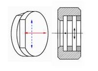
All standard catalog Meadowlark Optics retarders are made from birefringent, uniaxial materials having two different
refractive indices – the extraordinary index ne and the ordinary index no. The difference between the two indices defines the material birefringence. Light traveling through a retarder has a velocity v dependent upon its polarisation direction given by
v = c/n
where c is the speed of light in a vacuum and n is the refractive index parallel to that polarisation direction.
By definition, ne > no for a positive uniaxial material. For a positive uniaxial material, the extraordinary axis is referred to as the slow axis, while the ordinary axis is referred to as the fast axis. Light polarised parallel to the fast axis travels at a higher velocity than light parallel to the orthogonal slow axis.
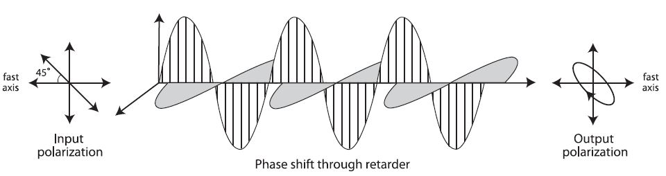
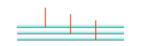
In the figure above, a plane polarised light wave incident on a birefringent material is vectorially decomposed into two
orthogonal components vibrating along the fast and slow axes. Plane polarised light is oriented at 45° relative to the fast axis of the retarder. The orthogonal polarisation components travel through the material with different velocities (due to birefringence) and are phase shifted relative to each other producing a modified polarisation state. The transmitted light leaves the retarder elliptically polarised.
Retardance (in waves) is given by:
δ = βt/λ
where:
β = birefringence (ne – no)
λ = wavelength of incident light (in nanometers)
t = thickness of birefringent element (in nanometers)
Retardance can also be expressed in units of length, the distance that one polarisation component is delayed relative to the other. Retardance is then represented by:
δ’ = δλ =βt
where δ’ is the retardance (in nanometers).
This equation illustrates that retardance is strongly dependent upon both incident wavelength and retarder thickness.
All retarders suffer small retardance oscillations as a function of wavelength when a coherent light source is used. This etalon effect can be substantial, depending upon the thickness and surface reflections of the retarder.
Retarder Materials & Types
Birefringence is common in materials with anisotropic molecular order such as crystals (both solid and liquid) and
oriented polymers. Crystalline retarders are often made of mica, calcite, or most commonly, quartz. Retarders can be multiple-order (having several waves of retardance), compound zero-order, or true zero-order. True zero-order retarders are often preferred for the most demanding applications requiring retardance stability with wavelength, temperature and angle of incidence. A true zero-order retarder is thin and must have a low birefringence to be manufactured easily.
A review of several retarder types is presented below.
Quartz has a birefringence of ~0.0092 in the visible region.
From the equations shown above, a true zero-order quartz quarter waveplate for 550 nm operation is only 15 microns thick. Such a thin, fragile retarder presents handling difficulties in both fabrication and mounting.
More commonly, multiple-order quartz retarders having a whole number of waves plus the desired fractional retardance (typically quarter- or half-wave) are offered. Precision polishing of the quartz substrate provides excellent surface and transmitted wavefront quality. However, multiple-order retarders can be extremely sensitive to incident angle, wavelength and temperature. As a rule of thumb, the retardance (in waves) for a 1 mm thick quartz retarder varies by about -0.5% per °C. Quartz retarders are sometimes preferred for their durability and high transmission properties.
A compound zero-order quartz retarder improves performance by combining two multiple-order quartz waveplates with the desired retardance difference.
The fast axis of one plate is aligned with the slow axis of the other, cancelling the large retardance values and leaving only the desired fractional retardance difference (typically quarter- or half-wave). Thermal stability of compound zero-order quartz retarders is improved as temperature effects of the two retarders cancel.
Mica, a natural mineral, is cleaved to precise thicknesses offering true zero-order retarders. However, cleaving is difficult over large apertures and does not offer the necessary tolerance or spatial uniformity required for most applications. Also, the long term supply of optical quality mica is uncertain.
Polymer materials offer a lower birefringence than quartz and can therefore be made into true zero-order retarders of
reasonable thickness, such as our Raptor products. They are much less sensitive to incidence angle than either multiple- or compound zero-order quartz retarders. Birefringence dispersion (or variation with wavelength) varies with each polymer material. This factor is an important consideration when manufacturing polymer retarders.
Meadowlark Optics protects the polymer material using a proprietary lamination process between optically flat windows. This assembly provides the transmitted wavefront quality necessary for precision optical applications. We precisely orientate and layer several polymer sheets to make achromatic polymer retarders.
These polymer stacks are then laminated between optical flats. Achromatic polymer retarders offer the versatility needed for broadband applications with demanding performance requirements. When a retarder must have the same retardance at two wavelengths that are separated by a span too large for an achromatic retarder, then a dual wavelength retarder may be the answer. Some versions of dual wavelength retarders can also provide different specified retardances at two different wavelengths.
Liquid crystal retarders are electrically variable waveplates. Retardance is altered by applying a variable, low voltage
waveform. These retarders are made by placing a thin liquid crystal layer between parallel windows spaced a few microns apart. Different liquid crystal materials range in birefringence from 0.05 to 0.26, enabling fabrication of thin, true zero-order retarders in the visible to near infrared region.
Fresnel Rhombs use total internal reflection to create a phase shift between two orthogonal polarisation
components. Fresnel rhombs make excellent achromatic retarders.
Quarter-Wave Retarder
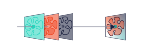
A quarter-wave retarder is used to convert light between circular and linear polarisation forms. It changes linearly polarised light to circularly polarised light, when the angle between the input polarisation and the retarder fast axis is 45°.
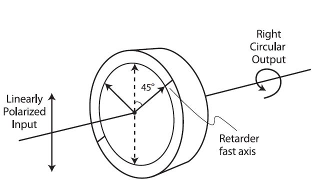
linearly polarised light is converted to righthand circular polarised light by the quarter-wave retarder. Upon exiting the quarter-wave retarder, light polarised parallel to the slow axis is retarded by 1/4 wave relative to light polarised along the fast axis. When recombined, the exit light is circularly polarised.
Similarly, this retarder orientation will convert input righthand circular polarised light to vertical linearly polarised
light for a reversed direction of travel.
Optical Isolator
A quarter-wave retarder is often combined with a linear polariser to form an optical isolator, used to eliminate
undesired reflections. A common application prevents unwanted reflected light from re-entering a laser cavity.
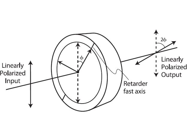
Half-Wave Retarder
Half-wave retarders are sometimes called polarisation rotators. A half-wave retarder flips the polarisation direction
of incoming light about the retarder fast axis. When the angle between the retarder fast axis and the input plane of
polarisation is 45°, horizontal polarised light is converted to vertical. A half-wave retarder rotates a linear polarised input by twice the angle between the retarder fast axis and the input plane of polarisation, as shown below:
A half-wave retarder can also be used to change the handedness of a left-circular polarised beam to right-circular
polarised, or vice versa. A half-wave retarder is also conveniently used to change the polarisation direction where mechanical rotation of a large laser is impractical.
Full-Wave Retarder
Full-wave retarders are valuable components for eliminating unwanted polarisation changes in an optical system. Many
optical components, especially metal mirrors, alter the polarisation state by introducing unwanted phase shifts. For
example, a linearly polarised input beam becomes elliptically polarised upon reflecting off of a metal surface. Ellipticity
can be accurately corrected by using a full-wave retarder and tilting it about either the fast or slow axis, to change its
retardance slightly.
Micro Retarders
PolyWave is a high birefringence polymer that enables ultra-thin retarders. Micro retarders passed rigid environmental testing with no change in retardance after many months of exposure to extreme conditions.
- Meadowlark Optics produces these retarders with dimensions less than 1 micron. The edges can be cut to allow the retarder to be used to within 15 mm of the edge.
- Due to the high birefringence of the PolyWave material, the total thickness of a 1550 nm half-wave retarder is only approximately 15 mm and a quarterwave retarder is approximately 8 mm thick.
Polarisation Control with Polymers
Naturally-occurring crystalline materials (calcite, mica and quartz) have traditionally been the birefringent materials of
choice for retarders. Today’s applications require performance versatility beyond the limitations of those crystals.
Meadowlark Optics specializes in the use of birefringent polymers and liquid crystals for polarisation control in precision optical applications. These innovative materials offer a unique combination of high performance
and cost-effectiveness.
Birefringent Polymers
Our polymer retarder assembly consists of birefringent polymer material laminated between two precision polished, optically flat BK 7 windows. Antireflection coatings and index matching optical cement help to maximize transmission in the visible to near infrared region.
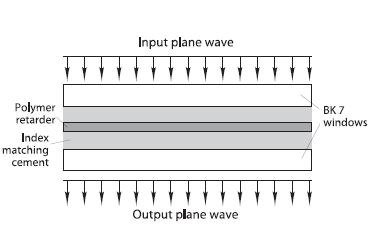
This construction ensures excellent transmitted wavefront quality, while minimizing beam deviation and surface reflection losses. Polymer retarders offer excellent angular field-of-view since they are true zero-order retarders.
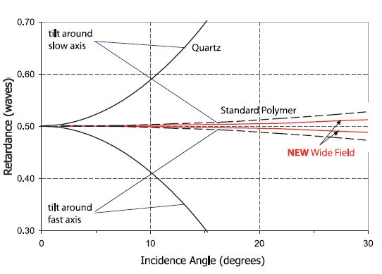
Comparing the change in retardance as a function of incidence angle for polymer and quartz retarders. A polymer retarder changes by less than 1% over a ± 10° incidence angle. Retardance accuracy with wavelength change is often a key concern. For example, an off-the-shelf diode laser has a center wavelength tolerance of ± 10 nm. Changes with temperature and drive conditions cause wavelength shifts which may alter performance. Meadowlark Optics polymer retarders maintain excellent retarder performance even with minor shifts in the source wavelength.
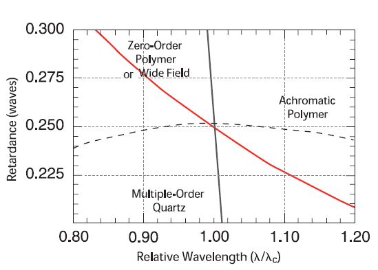
We also produce achromatic retarders with excellent retardance accuracy over a very broad wavelength range. Basic
construction of achromatic retarders is the same as that for zero-order polymer retarders. A comparison of different retarder types and their dependence on wavelength is shown below
The temperature sensitivity of laminated polymer retarders is about 0.04% per °C, allowing operation over moderate
temperature ranges without significantly degrading retardance accuracy. We can also thermally calibrate polymer retarders for specific operating temperatures.
Large aperture quartz retarders are difficult to fabricate and become cost-prohibitive beyond two inches in diameter. Meadowlark Optics polymer retarders with large apertures can be fabricated for a reasonable price. Please call for a custom quotation.
Polarisation Selection “Guide”
When choosing a polariser it is normally a balance of several key considerations: cost, wavelength range, aperture size, acceptance angle, damage threshold, transmission efficiency, and extinction ratio. A summary table can be seen below
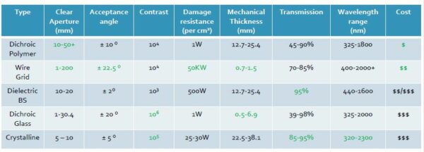
Choosing a polariser for an application, one must take all specifications into consideration. Usually, the customer knows several specifications of the desired polariser. These may include: transmission, contrast ratio, price range, wavelength range, mounting considerations, and transmitted wavefront quality. This will provide a basis for a recommendation as to which polariser will work best for the application. However, all specifications must be examined when choosing the ideal polariser.
Certain tradeoffs may have to be made to achieve a desired specification. For instance, if a customer wants a dichroic polymer polariser with excellent wavefront quality, they cannot obtain an unlaminated polariser.
Usually, identifying the application and the most important required specification is an ideal starting point for choosing a polariser. Not all applications place the same emphasis on the same specification. One of the first specifications to consider may be the wavelength or wavelength range of use. This can easily limit the types of polarisers from which to select, especially in the ultraviolet. Many polarisers are either opaque in ultraviolet light or are damaged by it. The target price must also be considered. Customers on tighter budgets will probably want to stay away from the dichroic glass and calcite polariser options as both of these options are significantly more expensive on the whole than the other three options.
Going through the decision making process on the type of polariser is a crucial step towards obtaining the optimal polariser. When one correctly identifies the required specifications for the desired application, choosing the polariser becomes much easier as each polariser has its strengths and weaknesses and all of the polarisers already have known applications where they work well with proven results. A knowledgeable sales engineer can help you with your questions through this selection process.
| Specification | Prefferred Type(s) of Polariser |
| Transmission | Dichroic Glass |
| Contrast Ratio | Dichroic Glass Crystalline |
| Clear Aperture | Wire Grid Dichroic Polymer |
| Transmitted Wavefront Distortion | Beamsplitting Wire Grid (with appropriate substrate) |
| Beam Deviation | Wire Grid |
| Laser Damage Threshold | Wire Grid |
| Thinnest | Dichroic Glass or Polymer Wire Grid |
| Cost (lowest) | Dichroic Polymer Wire Grid |
| Acceptance Angle | Wire Grid |
| Absorptive Polariser | Dichroic Glass or Polymer |
| Reflective Polariser | Wire Grid Beamsplitting Crystalline |
Frequently Asked Questions (FAQs)
Precision Retarders
My laser center wavelength varies by a few nanometers, but I need my retarder to be a nearly perfect quarter-wave of retardance for each wavelength in order to give maximum isolation. I’ll go broke if I have to purchase 10 retarders spaced at 0.5 nm intervals. Is there another way?
Solution
0.5 nanometers exceeds even our tight tolerance on retardance! Try angle tuning your retarder. A 10° tilt can change the retardance by about 1.25 nm or 0.002 waves of retardance at 632.8 nm. Remember to tilt about the fast or slow axis of your retarder, likely at ±45° to your optical bench. Another solution is to use a liquid crystal variable retarder.
I purchased a compound zero-order retarder for use in an imaging system where I need a good field of view. Do these really have the field of view of a true zero-order retarder
Solution
This is a common misconception. In fact, compound zero-order retarders are twice as bad as the multi-order retarders they are made from! If you need a good field of view, you must use a true zero-order retarder.
Dual Wavelength Retarders
I have a need for a quarter (or half) wave retarder at two different wavelengths. Which do I order, the Precision
Achromatic Retarder or the Dual Wavelength Retarder?
Solution
Dual wavelength retarders are primarily for use at two different wavelengths separated by 20% apart. If the
wavelengths are both covered by one of our standard achromatic retarder wavelength ranges we recommend purchasing a Precision Achromatic Retarder. We can also do custom achromatic retarder wavelength ranges. Please
contact us for assistance and a custom quote.
If the wavelength difference between the two is greater than 30 to 35 % of the lower wavelength, then we
recommend a Dual Wavelength Retarder.
“I need a Dual Wavelength Retarder with two non-standard retardances at two non-standard wavelengths. Can you help me?
Solution
While not all retardance and wavelength combinations are available, we can manufacture tens of thousands of
different combinations for our Dual Wavelength Retarders. Please contact our experts for a custom quote.
How to order dual wavelength retarders?
To order dual wavelength retarders, five pieces of information are required (with their symbols in brackets):
- The first (or lower) wavelength [λ1] in nanometers
- The second (or higher) wavelength [λ2] in nanometers
- The retardance at the first wavelength [R1], where:
- Q = Quarter wave retardance
- H = Half wave retardance
- F = Full wave retardance
- The retardance at the first wavelength [R2], where:
- Q = Quarter wave retardance
- H = Half wave retardance
- F = Full wave retardance
- The outside diameter, 0.50 in. or 1.00 in. [D], where:
- 050 = 0.50 in.
- 100 = 1.00 in.
The part number is then created by these five pieces of data and the letter “D” to start it off
D R1 R2 – D – λ1 / λ2