


A tutorial explaining full stepping, half stepping, and wave stepping.
Microstepping Theory
A bipolar stepper motor has two windings. The current through each winding is varied in order to rotate the stepper motor. When considering stepper motor drive techniques, a “phase diagram” is a useful visualization tool.
The current through one winding Ia is plotted against the current through the other winding Ib. Modes of operation such as full stepping, half stepping, micro stepping, and operation at different current limits can be easily visualized on such a diagram.
In addition, it is possible to visualize changes in both power consumption and torque as a function of angular position. Simple stepper motor controllers are only capable of driving a winding with full positive current, no current, or full negative current.
Given these available outputs it is only possible to implement full stepping, half stepping, or wave stepping.
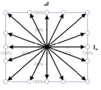
Full Stepping
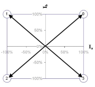
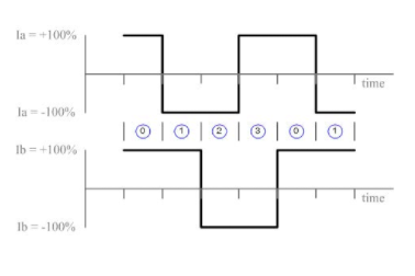
In full stepping operation, the current required in each winding is either -Imax or +Imax. A step sequence of 4 full steps makes up one complete step cycle.
Note that these full step positions are the same as the odd numbered positions from the half stepping sequence.
Phase diagram
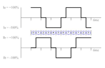
Timing Diagram
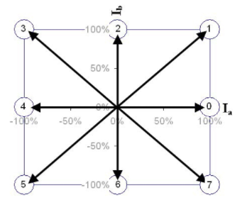
Half Stepping
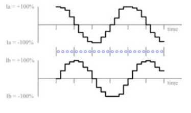
In a half stepping operation, the current required in each winding is either -Imax, 0, or +Imax. A step sequence of 8 half steps makes up one complete step cycle.
Phase diagram
Timing Diagram
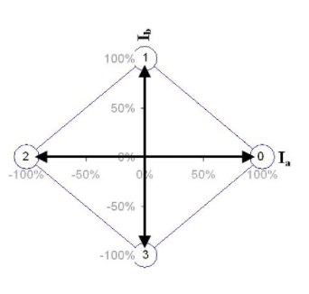
Wave Stepping
Wave stepping is another method of full stepping, but with reduced power requirements (and corresponding torque output) since only one winding is powered at a time.
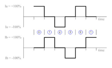
The current required in each winding is either -Imax, 0 or +Imax. A step sequence of 4 full steps makes up one complete step cycle.
Note that these full step positions are the same as the even numbered positions from the half stepping sequence.
Phase Diagram
Timing Diagram
The arrows in each phase diagram are called “phasors”. The angle theta that the phasor moves from one position to the next is the step or microstep angle.
On a phase diagram, 90° corresponds to one full step and 360° corresponds to a “full step sequence”.
A full step sequence is a sequence of steps or microsteps which, when repeated, will produce continuous rotation of the motor.
Assuming adequate torque, any continuous path which traverses the 4 quadrants of the phase diagram with at least one point per quadrant will suffice to rotate the stepper motor.
If the controller is designed with the capability to control the magnitude of the current in each winding, then microstepping can be implemented.
The phase diagrams below all show different implementations of “divide by 4” microstepping.
Note that it is the phasor angle (not its length) that determines the microstep position.
The phasor length affects power consumption and available torque as we will see later.
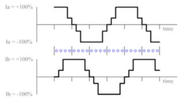
Microstepping – Square Path
This method of microstepping provides the highest peak torque if you are limited by available supply voltage.
Phase Diagram
Timing Diagram
Microstepping – Circular Path
This method is also referred to as sine cosine microstepping and is usually what people are referring to when they talk about microstepping, though in fact it is only one method.
Phase Diagram
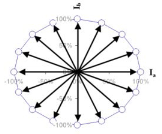
Timing Diagram

Microstepping – Arbitrary Path
There would be little reason to use a method such as this. It is presented only to illustrate the possibilities. Although it looks very strange compared to the other two methods, in theory it will produce the same angular rotation of an ideal motor. Only the available thrust would differ.
Phase Diagram
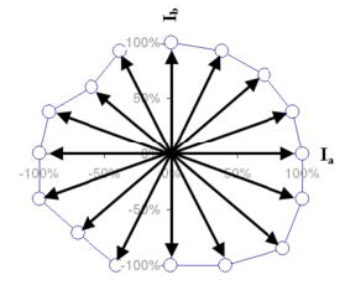
Timing Diagram
While it is convenient to think of the Ia and Ib axes as representing full step positions, it should be recognized that this is an arbitrary choice and any 4 positions in the phase diagram that are 90° apart from each other could be considered full step positions.
However, for the sake of simplicity, let us consider the positive Ia axis to represent theta = 0°. As theta increases, the phasor moves counter-clockwise from this position.
At theta = 90° the phasor lies along the positive Ib axis, one full step from it’s starting position.
Any angle theta between 0 and 90° represents a possible microstep position (a position between full step positions).
If you wish to implement “divide by 10” microstepping, then you must generate values of Ia and Ib that correspond to values of theta equal to 0, 9, 18, 27 … 81, 90°, etc.
theta = Tan-1(Ib/Ia)
There are many values of Ia and Ib that could be chosen to produce the same phasor angle theta. The choice of phasor length is typically decided based on the motor power rating and the application’s torque requirements.
Power and torque are both related to phasor length. The power draw at any given angular position is given by the formula:
power = Ia2R + Ib2R
where R is the winding resistance (both windings should have the same resistance)
The length of the phasor is given by the formula:
phasor_length = Sqrt(Ia2 + Ib2) = Sqrt(Power/R)
Thus the phasor length gives an indication of the power draw at each microstep angle. Torque is directly proportional to current (assuming magnetic saturation is not reached).
Thus, the available torque is directly proportional to phasor length, and the phase diagram gives an indication of how torque may vary with microstep position.
Aside: note that phasor length is proportion to torque and to Sqrt(Power). Therefore torque is proportional to Sqrt(Power). In other words, a 2x increase in torque requires a 4x increase in power (assuming magnetic saturation is not reached).
A phasor of constant length is typically used for smoothest operation (minimum torque ripple) and constant power output.
This results in a circular path around the phase diagram, the phasor length being the radius of the circle.
This technique is referred to as “sine cosine microstepping” because the target values for Ib and Ia are proportional to sin(theta) and cos(theta) respectively.
In practice, the term microstepping usually refers to sine cosine microstepping, but in theory, sine cosine microstepping is only one method of microstepping.
As mentioned above, a functioning microstepping algorithm may be designed around any arbitrary path which traverses the 4 quadrants of the phase diagram and has at least one point per quadrant.
The maximum continuous power output of a motor is usually specified by the manufacturer. This places an upper limit on phasor length, sqrt(Ia2 + Ib2).
The effective limit that this places on Ia and Ib will depend on the geometry of the path chosen around the phase diagram.
One must also consider the limitations of the power supply being used to drive the motor. In voltage-controlled products, the maximum values of Ia and Ib may be limited by the power supply voltage (I=V/R).
In this case, using a square phase profile is a way to achieve higher torque without requiring a higher voltage power supply.
Zaber devices are driven in a circular phase path to achieve smooth motion and constant power output. This internal processing is what allows compact motorised linear stages to achieve high precision without relying on external driver boxes. The current limit is user configurable and specifies the value of Ia at theta = 0.
In some Zaber devices (T-Series), square phase mode is also available.
Square phase mode offers about 40% higher torque for the same current limit. However there is a price to pay and that is torque ripple.
You can see that as you move around the phase diagram along a square path, the torque (proportional to the length of the phasor) will be constantly increasing and decreasing.
This results in less smoothness of operation and less microstepping accuracy. Generally, it is easier to achieve higher torque simply by increasing the current limit.
However, sometimes, your maximum current limit is restricted by your supply voltage, or the capabilities of your controller. In this case, reduced smoothness and accuracy may be an acceptable compromise for additional torque.
Source of Error in Microstepping Systems
Stepper motor control systems are usually open loop. That is, the controller does not have position feedback and therefore is not aware of the “actual” position of the motor.
Therefore, it is important to be aware of possible sources of error that will result in the actual position being different from the calculated position.
Quantization Error
In any digital controller, it is impossible to achieve infinitely variable Ia and/or Ib. Only discrete or “quantized” values are possible.
The number of discrete values depends on the resolution achievable by the controller.
For example, if the maximum current output of the controller is 1 A, and the controller has a resolution of 0.1 A, then there are 10 possible current values for Ia and/or Ib, not including 0.
The number of discrete values possible determines how close mathematically the phasor can be set to a particular length and microstep angle.
The error between the desired phasor angle and the actual phasor angle achieved is the quantization error.
A maximum quantization error equivalent to 0.5 microsteps is a typical design requirement in any microstepping control algorithm.
Note that by adusting the phasor end point to a nearby Ia,Ib point rather than sticking to a strictly circular or square profile can often reduce the quantization error, but may add some torque ripple.
Thus, the current resolution you require for Ia and Ib will be determined by the number of microsteps per step you want to achieve, the quantization error you can tolerate, and the torque ripple you can tolerate.
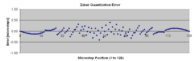
In Zaber’s stepper motor control algorithm, our design requirements were 128 microsteps per step with a quantization error less than 0.5 microsteps, and a torque ripple less than 2.5%.
Determining how many discrete current values are required for Ia and Ib is a task best left to a spreadsheet application, such as Excel.
Even then, it requires a certain degree of trial and error. As it turns out, 80 discrete current settings (between 0 and the running current) are required to achieve 128 microsteps per step with a quantization error less than 0.5 microsteps, and a torque ripple less than 2.5%.
The resulting quantization error at each microstep position is plotted below in Figure 1.
Detent Error
Detent torque is the maximum torque that can be applied to an unenergized stepper motor without causing continuous rotation.
If you plotted torque versus shaft angle as you slowly rotate the stepper motor with no current in either winding, then you would find that the torque is approximately sinusoidal with shaft angle.
The detent torque is just the amplitude of the sine curve. In an ideal motor, the torque curve would be perfectly sinusoidal.
What is commonly referred to as “detent error” isn’t due to the existence of the detent torque per se but due to the non-sinusoidal component of the detent torque.
The shape of the torque curve is affected by motor pole geometry. In that sense, detent error is really pole geometry error.
Because different motor manufacturers use different pole geometries, this error can vary from one manufacturer to another as well as from one motor to another.
Leadscrew Pitch Error
Many motorized systems convert rotary motion to linear motion via leadscrew. Stepper motor applications are no exception. In these types of systems, any error in the leadscrew pitch will contribute to the total system error.
Sticktion and Backlash Error
In microstepping systems, mechanical sticktion and backlash are frequently much larger than the microstep resolution.
There are many systems on the market capable of microstepping at 256 microsteps per step, but there is little point to this if mechanical sticktion in the system will be on the order of 5 to 10 microsteps at that microstep resolution.
Sources of Failure in Microstepping Systems
This discussion has centred on the challenges of designing a microstepping system, but there are also challenges when implementing a system.
If the load on a stepper motor exceeds its maximum torque, then the motor poles will not follow the changing magnetic field and the motor stalls.
To avoid this type of failure, microstepping systems must either keep the load below the maximum torque, or include position sensors to detect and compensate for stalls.
Other Blogs/Articles that may be of interest:
- Why is Mid-IR Light so Important?
- Engineered Point Spread Functions (PSF) for Single Molecule Localisation Microscopy (SMLM)
- Nanoscopy for less than £100k?
- Understanding the jargon of LCOS Spatial Light Modulators (SLMs)
- Spatial Light Modulator Applications
Zaber Technologies is a manufacturer of high-precision positioning devices and systems. In the late 1990’s, Zaber introduced the world’s first precision linear actuator with all control and drive electronics integrated into one compact package. Since then, Zaber’s product line has grown to include a wide range of motion devices, most with optional built-in controllers and drivers. For more information, contact us here: