


Optical filters are used in a myriad of applications such as DNA Sequencing, Fluorescence Microscopy & Imaging, Flow Cytometry, High-throughput Screening, Point-of-care Diagnostics, Raman & FTIR Spectroscopy and Optical Coherence Tomography. This blog explores the cost drivers of implementing a custom filter into a product, and puts to bed the myth that custom has to mean costly. Written by Toby Scrivener.
We will cover the following topics:
- Introduction to why you should want custom over catalogue.
- High, Medium, and Low cost drivers.
- Why you can trust Laser 2000 and Semrock.
Written by Toby Scrivener
10-15 minutes read

If you have been put off moving from a catalogue filter to a custom filter, then this is an article for you. In this blog we explore the main cost drivers and the reasons why you should use Semrock for custom filters to save money, reduce complexity, and secure your supply chain.
1. Introduction
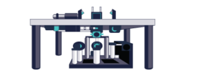
You’ve designed a product, it’s revolutionary, novel, and the prototype works! The only problem? It’s a massive table top of cluttered, catalogue optics, with huge unused space between. By using bespoke optics, designed specifically for your product and technique you can:
• Reduce the size of your system, • Reduce the cost, • Reduce complexity, • Protect your supply chain
Below we investigate and discuss the specifications of optical filters, the cost drivers, and the reasons why you should always use custom optical filters where possible and move away from catalogue parts.
2. Main Costs and a Collaborative Approach
Laser 2000 has always taken pride in its method of helping customers through a collaborative partnership. We help through the whole process from conception of a new product or an upgrade or improvement on an existing system, all the way to delivering in non-standard packaging.
The iterative process of discussing and adjusting the specifications to offer the best performance for the application, whilst reducing the overall cost, is an exercise that requires input from everyone. From the customer, the sales engineer, the optical engineers, the QA team, and even the logistics team.
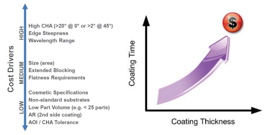
It is shown in figure 1 that we can divide certain specifications into high, medium, and low cost drivers. In this article we will explore these specifications and cost drivers in greater detail.
High cost drivers
AOI and CHA
Angle of Incidence, or AOI, is the angle at which a collimated beam of light is incident on the filter’s first surface, measured relative to the surface normal. Cone half-angle, or CHA, refers to the angular range associated with a non-collimated incident beam, and is measured from the AOI to the largest cone angle. Changing the AOI or CHA of your incident light will change the spectral response of the filter.
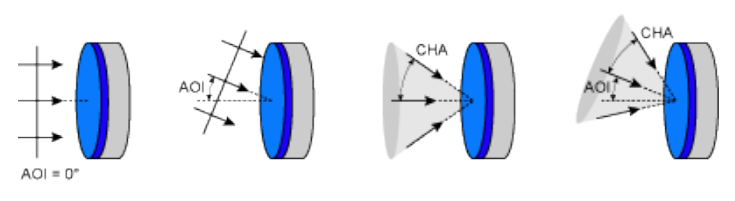
Figure 3 shows that using a standard catalogue filter that has not been designed to be used with large CHA light sources will have disastrous results, as can be seen on the expected performance (green) vs the realised performance (red). The second design has considered this large CHA variance and so the performance is markedly improved. Similarly, out of band blocking and edge steepness is improved with a custom filter, as shown in Figure 4.
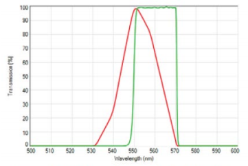
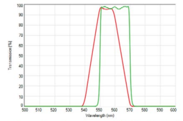
Figure 3 – A standard filter without considerations to CHA shows reduced transmission performance, compared to a custom-designed filter with a high tolerance to high CHA.
Here a high CHA would be considered as anything above 20o at 0o AOI, or >2o at 45o AOI.
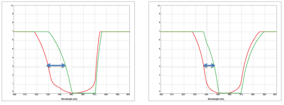
Figure 4 – Out of band blocking and edge steepness is also improved when CHA is compensated with a custom filter.
It is extremely important when discussing the requirement of your filter that CHA and AOI are distinguished between. For example, specifying a given AOI range is not the same as specifying a filter with the same value of CHA.
If we take the LL01-785 as a test subject, and change the expected AOI of the incoming light, we can see in Figure 5 that the overall spectral performance of the MaxLine Laser Line filter tracks well as the AOI is increased from 0°. However the performance quickly degrades with in increasing CHA. This effect can be addressed through different design approaches.
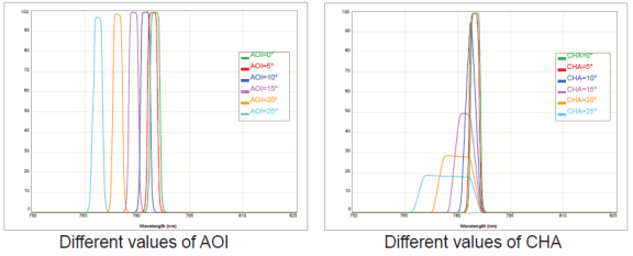
Figure 5 – The effect of a varied AOI is very different to a varied CHA on this MaxLine Laser Line filter.
Edge Steepness/Transition Width
Creating steeper edges on your filter, which are the points where the filter goes between blocking to transmitting, is a high-cost driver. If you need high edge steepness, this requires more coating layers which takes time, and this time increases the costs associated with the coating.
Transition width and edge steepness are two terms often used to describe the spectral properties of edge filters and it is important to know that these two terms are related, but not interchangeable. Transition Width is the maximum distance between the laser line (where OD>6) and the 50% transmission point. Edge Steepness is the actual distance between the place where OD>6 ends and the 50% transmission point.
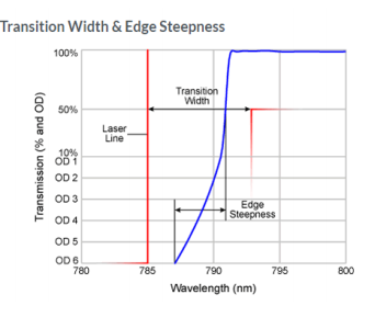
Figure 6 – The difference between Transition Width and Edge Steepness.
Wavelength Range
One of the biggest and sometimes most unavoidable cost drivers are the spectral range that you need the filter to be designed to. Moving to the extreme ends of the range of 200nm-2000nm can increase the costs of coating runs.
Working in the extreme UV requires unique substrates, which require slower deposition rates. This creates a longer “door-to-door” times. In contrast, the IR range uses VIS materials, but thicker coatings are required to achieve the same spectral performance. Going from 600nm to 1200nm doubles the layer thickness required.
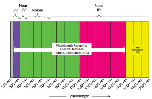
Figure 7 – The spectral zones in which your features are designed have different associated costs.
Medium cost drivers
Flatness Requirements
Flatness is the actual physical deviation of a component surface from a perfectly perpendicular plane. This is demonstrated in Figure 8. Flatness can be important in some applications that require the beam shape, or image created by the reflected light, to be maintained, i.e. a low Reflected Wavefront Error (RWE). The RWE is the deviation of a wavefront reflected off a component surface relative to a perfect wavefront reflected off of a perfectly plane surface.
At normal incidence, the flatness and RWE are simply related by a factor of 2. At Non-normal incidence, the relationship between the flatness and RWE depends on the angle of incidence.
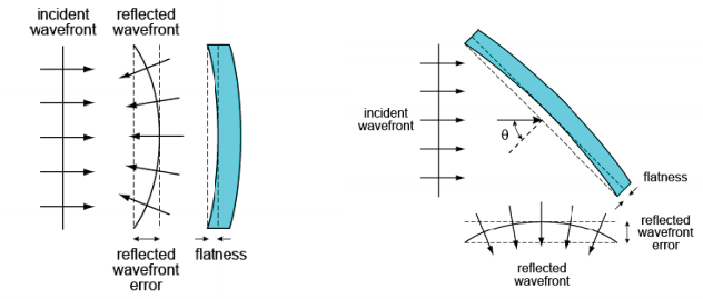
Figure 8 – Examples of RWE caused by not stress compensating the optical coating.
If the filter you are designing requires a good flatness specification, then a stress compensating coating is required. This coating can be a similar thickness to the functional coating, and essentially balances the forces on each side of the filter to make it flat. This takes more time in the coating chamber, and so drives the cost higher. The cost can sometimes be mitigated if a thicker substrate can be utilised.
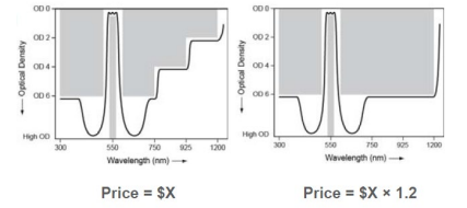
Extended Blocking/ Deeper Blocking
By truly understanding the customers system, we are able to suggest cost saving alternatives when it comes to blocking. In a lot of cases, customers ask for the highest level of blocking in the areas outside of their area of interest. However by using a stepped approach, considering the levels of light in that region of the spectrum, as well as the sensitivity of the sensor, large costs can be mitigated. This is shown in figure 8 below.
Part Size (area)
Sometimes area can be the easiest way to reduce cost. It can go without saying that a smaller optical filter, can in most cases be assumed to cost less than a large one, especially if it has a large volume (quantity) to support it. However there is a tightrope to be walked. Larger parts can be more challenging to make and the costs typically do not scale linearly. In some cases, they can scale by the area. Conversely, parts smaller than 5mm can also be challenging in terms of manufacturing, handling and packaging.
Through the consultative process of the design stage we can advise you the best size optic for your application, as well as the filter design.
Low cost drivers
Cosmetic specifications
Scratch and Dig There are a whole host of requirements that could considered to be a cosmetic specification. One of the more significant specifications would be Scratch-Dig. Semrock relies upon the definitions and inspection techniques established by the American National Standard Institute (ANSI) contained in standard ANSI/OEOSC OP1.002-2009.
Scratch – “A marking or tearing of the optical surface that has a v-groove contour that is significantly longer in dimension than it is wide… it is a long imperfection.” Scratches are characterized by their width, and the customer defines their requirement by specifying the maximum width for a scratch located within the clear aperture (CA) of the filter. (i.e. a “60” scratch designation establishes 60 microns as the maximum allowable width of a scratch located in the CA of the filter.)
Dig – “round and sometimes irregular shaped holes or voids (pinholes); including grinding pits and opened entrapped bubbles.” Digs are characterized by their actual diameters specified in units of 10 microns and the customer defines their requirement by specifying the maximum diameter for a dig located within the CA of the filter. (i.e. a “40” dig designation establishes 400 microns as the maximum allowable width of a dig located in the CA of the filter.) As defined in the standard, either a 40 watt incandescent lamp or two 15 watt fluorescent lamps are used to illuminate the test units against a black background. Each filter is inspected by eye and compared to a Comparison Standard. During the test, the parts are held under the lamp at a 45° angle of incidence relative to the associate’s eye. You can see this process in action here.
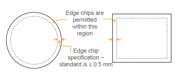
Edge Chip & Clear Aperture When parts are cut from the coated substrate, the cutting tool can dislodge some of the coating. This may result in small edge chips. Semrock’s standard specification, as per ANSI/OEOSC OP1.0022009, requires all edge chips lie no further than 0.5mm from the part edge, but other specifications are possible on request.
Edge Blackening and Part Marking Edge blackening serves the purpose of preventing or reducing light leakage through the rim or edge for unhoused parts. The process of applying an edge blackening is done by hand for small volumes and this can drive cost. In addition to this, edge blackening may not be suitable if the part is too small.
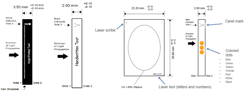
Catalogue parts of a standard size of 25mm⌀ or 12.7mm⌀ can be built into an aluminium ring housing. These rings can be inkjet printed with your choice of text, and an arrow indicating the direction of light propagation. Alternatively, parts that are not suitable for a housing ring, can have handwritten text applied, or a caret, again indicating the direction of light propagation.
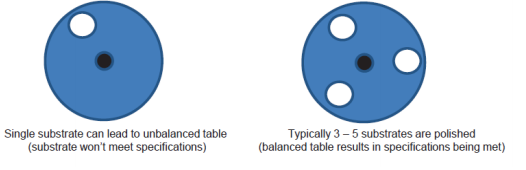
Non-standard substrates If the optical filter you are planning on using requires a non-standard substrate, for whatever reason, then it is possible that additional substrate may needed to be polished at the same time. This is required to balance out the polishing table. Without this balanced approach, it is unlikely that the target specifications can be met. This will ultimately lead to an increase in price and leadtime.
AR (2nd side coating) An AR coating on one side of a substrate is another associated cost with creating an optical filter. Fortunately, these coatings are considerably shallower than optical coatings, so the time taken to coat is less than a custom coating. This is why it is a low cost driver.
Other Considerations We can also consider other qualities and specifications that might be important. These include but are not limited to, GDD Compensation, Zero Pixel Shift, Polarisation specifications etc. If there are any considerations that you think are significant for your application, you should discuss these with your sales representative.
3. Why Laser 2000 and Why Semrock?
Laser 2000 has always prided itself in continuously improving customer satisfaction, and Semrock is no different when it comes to its supply chain management and manufacturing processes. Both Semrock and Laser 2000 ensure that rigorous documentation and revision control is in place in all of their processes. Whilst parts are in manufacturing, and once parts have been manufactured, there is complete traceability and product histories for each part. By knowing the history and constantly measuring and monitoring stock levels, inventory is kept at a level that will satisfy a customer’s delivery goals.
Whatever your preference, Laser 2000 and Semrock can offer filters that meet specifications and arrive as part of a blanket order, purchasing contract, or just-in-time delivery. We can produce a variety of filters that are suitable for a number of applications. Below is a list of some examples of standard products we offer from our catalogue, as well as that we can offer as custom solutions:
- Fluorescence filters
- Raman spectroscopy filters
- Tunable bandpass filters
- Deep notch filters
- Laser-line filters
- Laser diode clean-up filters
- Filters to combine or separate laser beams
- Filters to isolate popular mercury lamp lines
- Polarization filters
- Dispersion controlled coating designs
- Laser mirrors
If you have a requirement for a custom solution then consider below a list of our core strengths:
- Wavelength functionality to specification, 230 nm − 2000 nm
- Ability to produce 10’s of thousands of parts per month
- Sizes down to 1 mm2 on 0.5 mm thick glass, and as large as 200 mm.
- Spectrally complex custom designs for customers (e.g. LED optimized filter designs)
- Custom sizing – Round, square, or rectangular, from several mm to a few inches
- Product labelling – On-filter laser engraving for easy identification and storage
Our manufacturing facilities use state-of-the-art coating chambers in protected cleanroom environments. Our Thin-film sputtering deposits low-loss, precise-thickness, and reliable optical thickness layers. Semrock has made it viable for high-volume production using our proprietary processes and optical monitoring technology. They are currently expanding to meet increasing demand and planning for continued growth.
Semrock optical filters have the highest transmission specifications, yielding better contrast and faster measurements, even at ultraviolet (UV) wavelengths. Maximum transmission, optimized blocking and the steepest edges give Semrock filters market-leading performance.
Semrock filters:
- Are impervious to humidity and temperature induced degradation
- Have lasting high level of performance, backed by field data proven 10-year warranty
- Meet or exceed requirements for environmental and physical durability in MIL-STD-810F, MIL-C-48497A, MIL-C-675C, and ISO 9022-2.
- Eliminate replacement costs, decreasing the cost of ownership
- Return rate is 0.3% (industry standard is 1%) you don’t need to worry about unreliable parts with Semrock.
The performance of Semrock catalogue parts are world leading, and they offer resized parts as a standard service, so why would you go to the effort of changing to a custom part? In the introduction we mentioned 4 reasons why you might consider moving to a custom optic. They were:
- Reduce the size of your system – By designing custom optics with your size specifications in mind you can use a smaller space to fit optics closer, or fit more optics into a smaller space.
- Reduce the cost – By going through the consultative process of working out the required specifications, taking into account the high, medium and low cost drivers, we can reduce the cost of a custom filter to that of a standard catalogue part
- Reduce complexity – By designing the filter with your optical requirements in mind, we can potentially reduce the number of optical filters, improve the performance, or work to creating a beam path that works for you.
- Protect your supply chain – By getting custom filters and committing to longer term contracts you can guarantee that your part will always meet your specification. There are no chances that changes to a catalogue part will impact your product. We will take your needs into account when instigating any change within the coating facility (i.e. change of coating machine, maintenance, etc.)
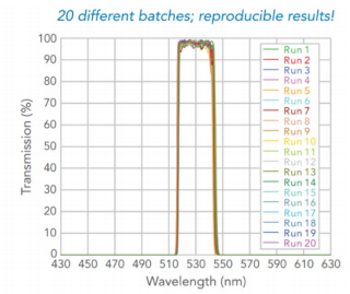
Whether a filter is from the first lot or the last, its spectral properties are the same. Our OEM customers can rely on a secure and dependable supply line. Figure 13 – Optical performance of the same filter from 20 different coating runs, showing reproducible performance.
If you want to:
- Reduce the size of your system,
- Reduce the cost,
- Reduce complexity,
- Protect your supply chain.
And are ready to discuss your requirements for custom or standard filters, get in touch today.
Contact us here:
Other Blogs/Articles that may be of interest
- Tilted Light Sheet with DHO PSF Engineering for 3D Whole Cell and Sub-Cellular Super Resolution Imaging
- Understanding the jargon of LCOS Spatial Light Modulators (SLMs)
- Spatial Light Modulator Applications
- Fluorescence Microscopy Light Source: LED vs Bulbs
- Confocal Microscopy – The Re-Scan Confocal Microscope (RCM)
- What are the benefits of using a fixed Femtosecond Fibre Laser in Two-Photon microscopy