


By Zaber Technologies
Introduction
Do you remember the large, heavy, color TV sets that were used until the early 2000’s? Many of us have been using vacuum technology without even knowing it. Those large TV’s all required a high vacuum cathode ray tube (CRT) to allow electrons to fly freely without colliding with other molecules.
One of the earliest significant uses for vacuum was to manufacture cathode ray tubes in the early 1900s, but the first use of CRTs was in an oscilloscope known as the cathode ray oscilloscope. As technology has advanced, the use of vacuum systems has flourished into a variety of different applications, such as electron tube manufacturing and optical coating. It was then discovered that many applications could achieve better results within vacuum than understandard atmospheric pressures, and in some cases achieve results that were otherwise impossible at the time. With the proliferation of vacuum applications, we have also seen an increased demand for vacuum compatible positioning equipment.
This article will outline the basics of a vacuum system and present considerations to keep in mind when gathering requirements for your application. It will focus on motion control and what is essential to achieve reliable performance without compromising the vacuum requirements.
What is a vacuum and why it is necessary
A vacuum, in engineering or applied physics, is an area with a lower than standard atmospheric pressure. In markets such as photonics and optics, industrial manufacturing, and life sciences, there are an increasing number of processes that must be performed under vacuum conditions. Ideal vacuums provide clean and contaminant free environments for research and manufacturing, such as optical coating, semiconductor manufacturing, and electron beam welding.
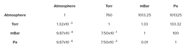
There are several standardised units used to specify pressure, including torr, milliBar (mBar), and pascals (Pa). Defining a vacuum pressure in terms of standard atmospheric pressure is also common. The relationship between these common units are found in Table 1.
Zaber currently manufactures low vacuum and high vacuum products. Their low vacuum devices are compatible under vacuum conditions as low as 10 -3 Torr, while their high vacuum devices are acceptable down to vacuum pressures as low as 10 -6 Torr. Higher levels of vacuum – such as ultra-high vacuum (UHV) that is designed to reach 10 -9 Torr — have more stringent requirements relative to low and high vacuum. UHV will not be discussed in detail in this article since our current focus within vacuum systems are in the low and high vacuum pressure range.
Different applications require specific vacuum ranges. Low vacuum applications include brazing, sintering, and mass spectrometry. High vacuum applications involve optical equipment as well as thin film coating and scanning electron microscopy. Some UHV applications include larger particle accelerators and photo electric research.
There are many applications that use vacuum levels ranging from atmospheric pressure down to 10 -1 Torr in which standard Zaber products can be used. This is dependent on the application’s requirements. Some applications include the use of carbon dioxide lasers and manufacturing neon and fluorescent lamps or incandescent light bulbs.
What to consider when selecting a vacuum compatible positioner?
There are several considerations that need to be addressed in order to achieve the desired vacuum level as well as a clean and contaminant free environment. Among these considerations are outgassing, material selection, heat management, virtual leaks, and cable management. This article will cover the basic considerations of vacuum systems and how Zaber have optimised their vacuum product lineup.
Outgassing
Outgassing is the release of molecules that have adsorbed onto a surface, absorbed into a material, or that are inherent as a property of the material. Adsorbtion is a collection of molecules that create a thin film on the surface of a material. Absorption is when a foreign substance is “soaked in” to a material. Any surface within a vacuum is considered a potential source of outgassing since surfaces are active areas for adsorption and absorption to occur.
Controlling outgassing is one of many challenges when maintaining a vacuum system. Outgassing vapours can deposit on sensitive optical equipment, create impurities in coatings, or contaminate a sample.
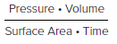
The outgassing rate, in combination with the pump down rate, determines the length of time it will take to reach the desired vacuum level as well as what vacuum level is achievable. Outgassing rate is defined by:
Water, grease, oil, and organic materials are a few of the more common outgassing vapours. The outgassing of volatile condensable materials such as hydrocarbons is often more of a concern than other types of molecules such as water vapour. Hydrocarbon vapours can condense on optical components and interfere with their operation, while water vapour generally does not condense and is effectively pumped out of the chamber.
When designing a device to go into a vacuum chamber, regardless of the material used, the outgassing rate is still Pressure x Volume per Surface Area per Time. Since the exposed surface area can adsorb a thin film of molecules, which will affect outgassing and pump down time, it is highly recommended to minimize the surface area as much as possible. This becomes a larger consideration in UHV systems.
Material Selection
As mentioned in the section on outgassing, materials will inherently outgas; therefore, material selection will play a large role in achieving the required vacuum level.
Materials have a property known as vapour pressure. The vapour pressure relates the temperature with the pressure exerted by a vapour in a closed system. If the pressure exerted is high, this will restrict your vacuum system from reaching a low vacuum level. Your ideal material should have a low vapour pressure, which results in low outgassing, and, therefore, a lower vacuum pressure.
A few examples of materials that have a high vapour pressure, and should be avoided:
- Porous ceramics
- Porous metals
- Plastics
- Adhesives
- Standard lubricants
- Standard oils
- Standard grease
- Organic material
Some materials with a low vapour pressure, and are good choices for vacuum:
- Stainless steel
- Austenitic steel
- Aluminum
- PEEK
- PTFE
- Kapton
- Bronze*
*Alloys such as brass or bronze contain zinc, which has relatively high vapour pressure when compared to stainless steel. The vapour pressure of zinc is less than 10 -11 Torr at 50°C, or 10 -6 Torr at ~180°C. This emphasizes the importance of material selection given the application requirements.
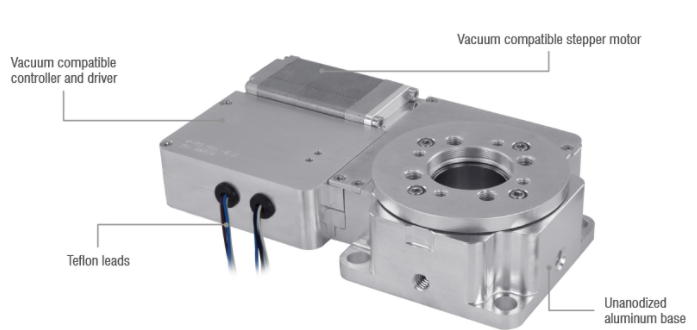
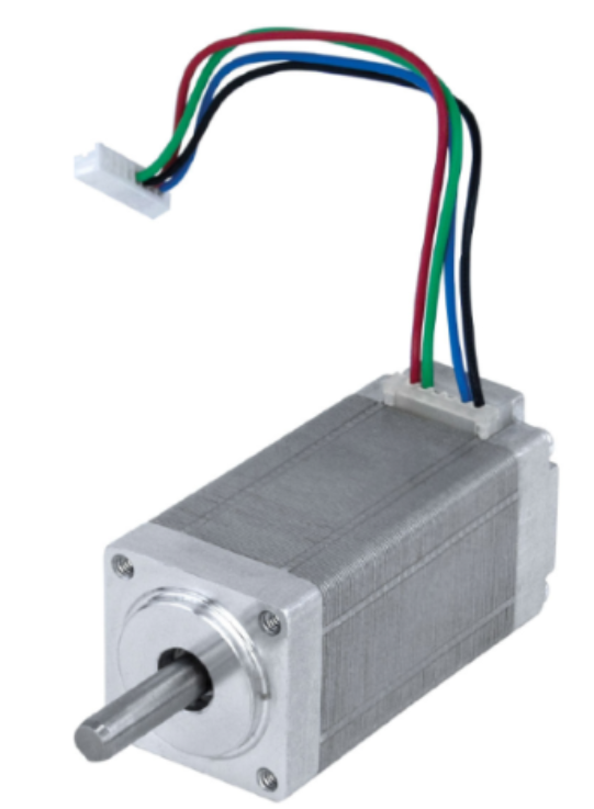
Standard stepper motors are generally not suitable for vacuum applications as their bearings can be coated with an oil or grease that has a high vapour pressure, and their wires can be insulated with PVC. Replacing the PVC insulated wires to PTFE/Teflon coated wires will help reduce outgassing. Vacuum motors often have their windings replaced for high temperature windings, and their paints and oils are removed and replaced with vacuum compatible greases, similar to the one shown in Figure 3.
In addition to motor wires, other electrical wires such as data cables should be replaced since standard wires are generally PVC insulated.
Standard sensors may also contain PVC insulated wires as well as plastic housings that have a high vapour pressure. These should be replaced with vacuum compatible sensors.
One unique advantage to using stepper motors in a vacuum is that they can be used without an encoder. Minimising the amount of electronics in a vacuum chamber is good practice, since electronics can fail in many ways including overheating.
Zaber carefully scrutinize all materials that are built into their products. They replace our motors with vacuum compatible stepper motors that use Teflon leads, special windings, and vacuum compatible lubricant and greases. All of their daisy-chaining cables also utilize Teflon insulated wires.
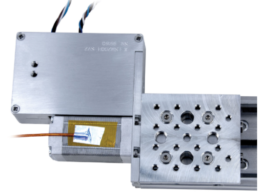
When electronics are required in a vacuum chamber, such as built-in controllers (as seen in Figure 1), they must be prepared for the expected vacuum level. Zaber replace any electrolytic capacitors with tantalum, and have the PCBs specially treated and manufactured to further reduce outgassing. An example of a high vacuum PCB is shown in Figure 4.
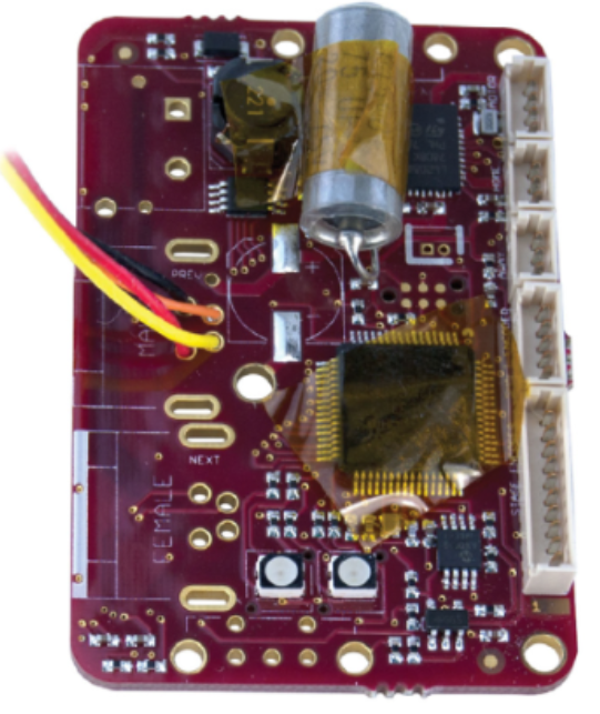
During manufacturing, Zaber’s vacuum PCBs are populated using a low residue flux, then cleaned with isopropyl alcohol multiple times prior to assembly.
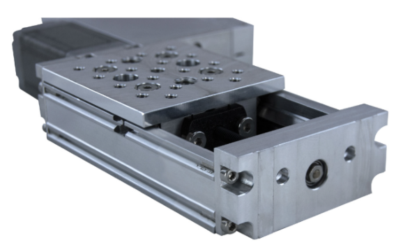
Standard Zaber devices use aluminum components that are hardened through a process called anodizing. Zaber’s vacuum devices are un-anodized because the anodized layer creates a porous surface that traps gasses and moisture more easily, resulting in more outgassing and longer pump down times. Figure 5 is an example of an un-anodized extrusion.
Heat Management
Without the fluid medium of air to dissipate heat by convection, electrical components in a vacuum must be carefully designed and monitored to avoid overheating. Exceeding the rated temperature for a motor or PCB can cause damage, make performance unreliable, and limit its lifetime.
As mentioned in the material selection section, Zaber’s vacuum motors are made to withstand a higher operating temperature within a vacuum, but they can exceed the rated temperatures without proper care.
Zaber’s vacuum devices use conduction as their primary source for heat dissipation. Mounting these devices to the chamber directly will also help heat to dissipate faster.
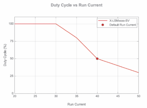
In addition, Zaber have optimised their PCBs and firmware to ensure that their devices maintain a temperature that produces reliable performance and optimal overall lifetime. This includes modifications to the PCB housing to increase heat sinking and modified firmware to control heat generation. When selecting a vacuum compatible Zaber device for your application, it is recommended that you contact our Zaber product manager to determine an appropriate duty cycle and running current combination. An example of a run current vs duty cycle plot can be found in Figure 6 below.
Zaber’s X-series vacuum devices have an integrated temperature sensor on their controllers; however, it is also recommended to add a sensor to the motor to monitor the temperature. For example, a K-type thermocouple or other temperature sensor may be mounted to the motor to monitor temperature in order to reduce the risk of overheating as seen in Figure 7 below.
Virtual Leaks
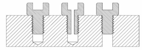
A virtual leak is a small pocket of trapped gas in a device that is linked to the larger vacuum chamber through a small channel. This causes a slow outgassing process that can prevent the vacuum chamber from reaching the desired pressure. An example of a virtual leak is a threaded hole with a fastener that is not vented. Figure 8 shows the difference between a blind hole, a vented screw, and a through hole.
Zaber carefully design their devices to minimise virtual leaks. They use vented screws and integrate venting paths in threaded holes to avoid trapped gasses. When possible, Zaber use a through hole rather than a blind hole. They also integrate venting slots on the controller housing, allowing trapped gasses to escape more quickly.
Cable Management
Because we have optimised our motorised linear stages with built-in controllers to withstand low and high vacuum pressure, they can be daisy-chained in a vacuum chamber. This means that multiple devices can share one power supply and a single connection to a computer, which reduces the number of wires to your feedthrough.
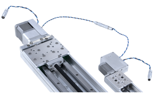
Zaber’s vacuum devices are shipped with non-vacuum compatible connectors, intended for initial testing and set-up. These connectors should be cut off, exposing the flying leads which can be crimped, tied, or soldered together to create a daisy-chain. Only four feedthrough wires (2 power, 2 data) are required for multi-axis motion in a vacuum chamber.
Alternatively, Zaber can provide vacuum compatible connectors (see Figure 9). Please contact our Zaber product manager for more details.
Set-up As Easy As 1-2-3
Setting up and controlling multiple Zaber devices in a vacuum chamber requires only a few steps (see Figure 10).
- Connect data and power cables between computer and vacuum chamber.
- Devices with built-in controllers receive power and data in the vacuum chamber via 4 feedthrough wires**.
- Send instructions or automate your set-up using Zaber Console.
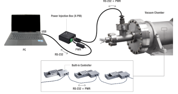
**For X-Series devices, power is injected via the X-PIB. For T-Series devices, power is injected via the T-DSUB9-P. If you are using an X-series device in a chain with a T-series device, the T-series devices will require an additional 2 wires for power injection.
Cleaning, Handling, and Packaging
As you decrease the vacuum pressure, the level of care and cleaning becomes increasingly important. Devices exposed to air are at risk of contamination due to adsorption on the surface.
Cleanroom gloves should always be worn when handling vacuum devices since bare hands can introduce oil, dirt, and other organic material. This can contaminate a vacuum chamber and produce unwanted excess outgassing.
Each component for Zaber’s low vacuum devices are degreased and cleaned using isopropyl alcohol, then assembled using cleanroom gloves.
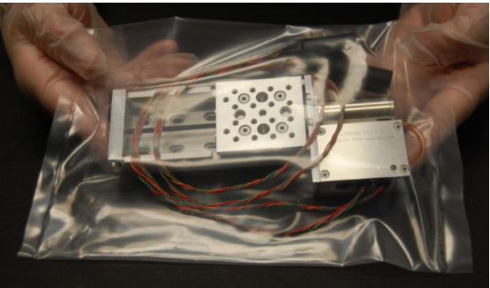
All components for Zaber’s high vacuum devices are ultrasonically cleaned prior to assembly. In addition to ultrasonically cleaning the components, the devices are assembled in a class 100 (ISO class 5) cleanroom. The parts do not leave the cleanroom until the finished products are packaged and ready to ship. When Zaber’s high vacuum devices are ready to ship, they are packaged in Ultra Low Outgassing (ULO®) polyethylene bags inside their cleanroom and double bagged, allowing the end user to remove the outer bag prior to inserting the device into their cleanroom. Figure 11 shows an example of a high vacuum device double bagged in ULO®.
Conclusion
Zaber are conscious of the strict requirements that vacuum systems and applications need. These considerations have been integrated into their vacuum product lineup in order to provide precision motion control without compromising vacuum application’s requirements. We are confident in their ability to provide reliable performance in low and high vacuum while maintaining their approach to simplifying motion control.
Written by Albert David, Applications Engineering Team
For more information please contact us here:
Other Blogs/Articles that may be of interest:
- Why is Mid-IR Light so Important?
- Engineered Point Spread Functions (PSF) for Single Molecule Localisation Microscopy (SMLM)
- Nanoscopy for less than £100k?
- Understanding the jargon of LCOS Spatial Light Modulators (SLMs)
- Spatial Light Modulator Applications