


Revolutionise Your Photonics Research with Our High-Performance LCOS SLMs
Do you know your Phase Ripple from your Phase level?
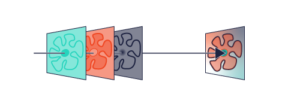
Spatial Light Modulators are among the most powerful optical components in modern photonics research — used in a wide range of spatial light modulator applications including adaptive optics, STED microscopy, optical trapping, holographic beam shaping, and femtosecond pulse compression.But specifying the wrong one for your application can mean wasted budget and compromised results.
Written by our SLM specialist, Peter Collins, this blog post is aimed to help you understand the fundamentals for specifying a new SLM and will focus mainly on Parallel Aligned Nematic devices.
We will cover the following topics:
- How does an LCOS SLM work?
- This section details exactly how an SLM works.
- How does an LCOS SLM work?
- Typical optical set-ups
- This section provides optical configurations when using an SLM in Phase, Amplitude, Twyman-Green Interferometer and in a 4f configuration for microscopy
- Typical optical set-ups
- In-depth review of the specifications to consider when purchasing an SLM
- This section goes into detail about the following specifications:
- Resolution:
- Pixel size pitch and the grating equation
- LUT Generation and electronic/optical phase levels
- Resolution:
- Diffraction efficiency:Zero and 1st Order
- Reflectivity and losses
- Blazed Gratings
- Computer-Generated Hologram (CGH)
- Diffraction efficiency:Zero and 1st Order
- Frame Rate:
- LC Response time
- Transfer Time
- Refresh Time
- Frame Rate:
- Precision:
- Spatially Varying phase response
- Time fluctuations/Phase flicker
- Precision:
- This section goes into detail about the following specifications:
- In-depth review of the specifications to consider when purchasing an SLM
- Why we think Meadowlark Optics SLM’s are the best available in the market today
- This section goes into detail on the following considerations:
- High Voltage Backplanes = Fastest Response Times
- Highest Phase Stability Commercially Available
- Low Inter-pixel Cross Talk
- Broad Wavelength Capabilities
- Analogue is Better
- High Bit Depth Controllers
- This section goes into detail on the following considerations:
- Why we think Meadowlark Optics SLM’s are the best available in the market today
1. How does an LCOS SLM work?
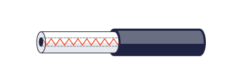
LCOS SLM stands for Liquid Crystal on Silicon Spatial Light Modulator. The liquid crystals are birefringent rod-shaped elements that are sandwiched between a pixilated Silicon backplane and a cover glass, as shown in figure 1.
SLMs can either be transmissive or reflective and can be used to alter Phase & Amplitude (individually or combined) and Polarisation of an incident light beam. This is like the LC flat panel display/TV you’ve got at home, which acts as an amplitude modulator to control the brightness and colour of the image.
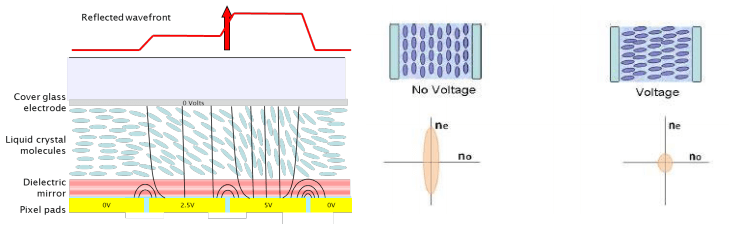
Each pixel is a capacitor, which are periodically charged with the required voltage. The LC molecules above each pixel rotate according to the applied voltage. The higher the voltage the faster and larger the rotation, up to 90 degrees.
As the LC molecules are birefringent, i.e. have a different index of refraction along at least 2 of the 3 axes, rotating the molecule results in changing the index of refraction but only in one polarisation state.
If the incoming light field is linearly polarised and aligned to the long axis (ne) of the liquid crystal the device acts as a Phase Modulator, because changing the refractive index changes the optical path length or speed at which the light travels.
If the light is linearly polarised and aligned at 45° to the long axis, it allows for retardance between the orthogonal ordinary and extraordinary axis, allowing for a polarisation change, as the polarisation state is the vector sum of the two orthogonal Electric vectors of the Electro-Magnetic wave.
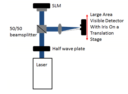
If the light from the SLM passes through a linear polariser, Amplitude modulation occurs due to the electronic control of the birefringence and hence the polarisation state, which can be seen in figure 2, which are typical experimental layouts
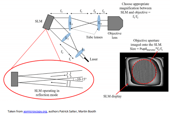
2. Typical Optical Set-Ups
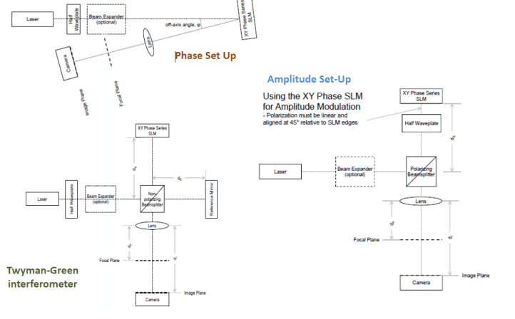
Typically, SLMs are used in Microscopy where the SLM is imaged in a 4f configuration with lenses L3 and L4 onto the back focal plane (pupil plane) of a microscope objective lens.
3. In-depth review of the specifications to consider when purchasing an SLM
As with all purchases the prices of different models can vary significantly in relation to the desired specification. Below is a list of purchasing considerations. However, before purchasing we strongly recommend speaking to our experts or try our loan unit for yourself. Loaning a unit from us is free of charge and can be typically borrowed for up to a week.
Not sure which application you need an SLM for? Browse our guide to spatial light modulator applications to find the right use case first.
- Resolution a. Pixel size pitch and the grating equation b. LUT Generation and electronic/optical phase levels
- Diffraction efficiency a. Zero and 1st Order b. Reflectivity and losses c. Blazed Gratings d. Computer-Generated Hologram (CGH)
- Frame Rate a. LC Response time b. Transfer Time c. Refresh Time
- Precision a. Spatially Varying phase response b. Time fluctuations/Phase flicker
- Damage Mechanisms and limitations
Looking at the above in more detail:
Resolution
Resolution is commonly described by two terms, spatial and phase resolution. Spatial resolution is the smallest resolvable diffracted angle which the SLM can steer a beam too, which is related to the pixel size/pitch, and phase resolution is the number of optically resolvable phase levels that can be achieved.
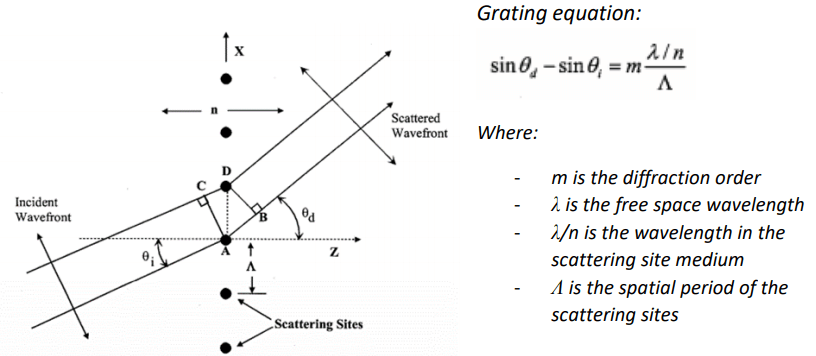
Pixel size pitch and the grating equation
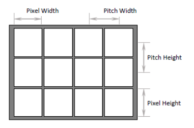
Fill factor is the percentage of Area within each pixel that is reflective.
Mathematically it is the (Pixel Width / Pitch Width) * (Pixel Height / Pitch Height).
When a beam of light passes through (reflected off) any periodic structure, it will be diffracted into multiple orders. Where the period of the repeated structure determines the angular separation, with a small period creating a larger angular separation.
When diffraction efficiency isn’t the main concern, the largest ‘steering angle’ is created by a binary grating added to the SLM where one column is 180 degrees out of phase to the next column (Efficiency ~ 40% for this type of grating).
For plane waves normal to the SLM surface the maximum steering angle in the above equation simplifies to:
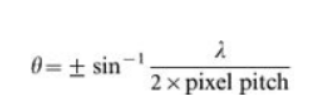
For Laser 2000’s high resolution 1920 SLM, the pixel pitch is 8.0 μm, so for a 1 μm you would see ~3.58 degree steering angle
Grating pitch does not need to be limited to the number of pixels in the SLM. If the grating pitch matches the number of pixels in the SLM it simply means the grating has only one period and it has a grating height is equal to one wave of phase stroke. A grating with more pixels per period will still be limited to one period on the SLM, but the grating height will be less than one wave. For example, on the 1920 SLM, if the grating pitch were 3840 pixels, then the grating height would be only 0.5 waves.
The minimum angle will come down to aberrations in the system and the ability to separate the 0th and 1st order such that the beam angle is resolvable.
LUT Generation and electronic/optical phase levels
A LUT is a ‘Look Up Table’ and is provided as a .LUT file, which the software uses to calibrate the SLM phase from 0 to 1 wave over the number of bits the controller has, typically 8, 12 or 16 corresponding to 256, 4096 or 65,536 electronically definable levels.
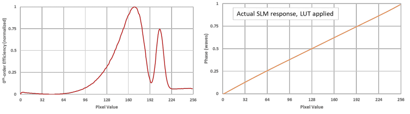
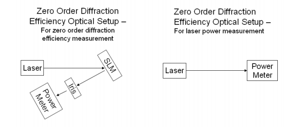
These LUT’s can be generated by the user using the software, where the SLM is loaded with a series of binary gratings. Each successive grating increments the phase value of one of the two binary grating values and either 0th-order or 1storder diffraction intensity is measured for each phase value increment (1st-order – maxima occur at π and 3π, 0th-order – maxima occur at 0π and 2π) and the algorithm converts intensity back to phase.
One common mistake is the assumption that the number of electronically resolvable phase levels is the same as the number of optically resolvable phase levels.
An optical phase level is the minimum number of Linear Phase Levels achievable with the selected SLM and Controller combination. Liquid crystal does not provide a linear response to applied voltage, therefore this number will always be lower than the bit-depth of the selected Controller.
As a rule of thumb if you have the 8-bit controller for the P512 model it provides 50 – 100 linear phase levels, the 8/12-bit controllers for the P1920 model provide 256 linear phase levels, and the 16-bit controllers for the P512 and 1x12k provide something greater than 500 linear phase levels, but we cannot readily measure the real resolution limit.
Diffraction efficiency
Zero and First Order
Diffraction Efficiency (zero-order) – This is the maximum percentage of light measured in the zero-order compared to the amount of light incident upon the SLM. This measurement accounts for all light lost through diffraction into higher orders or absorption by the various layers in the SLM.
Typically, this will be specified as a range since the measured efficiency changes as a function of applied pixel value as the liquid crystals rotate and present a different index of refraction causing a change in the Fresnel reflections at the liquid crystal cell boundaries.
Diffraction Efficiency (1st-order) – This is the maximum percentage of light measured in the 1st-order with a phase ramp compared to the light in the 0th order when no pattern is written to the SLM.
Reflectivity and losses
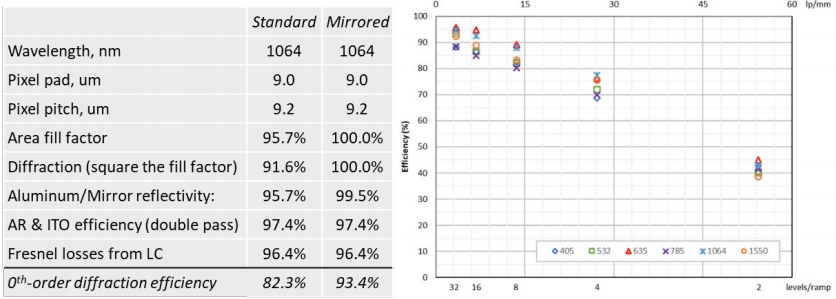
As mentioned in section 1, the pixel pads cause diffraction into multiple orders and theoretically the limit for the 0th order is the square of the fill factor. Standard devices use Aluminium pixel pads as the mirror, which though broadband varies with wavelength.
Adding a dielectric mirror coating over the Aluminium pixel pads can decrease the overall useable bandwidth of the light but can increase the fill factor and increase 0th -order efficiency to a range of 90 – 95%.
One issue to consider when applying a dielectric coating is that broadband coatings typically need more ¼ wave stacked layers which can cause more cross talk with reduced resolution and speed. If the dielectric stack is thinner, then some Etalon effects may be observed.
Cross talk is also referred to as field fringing is also a source of loss. It is when the liquid crystals long axis direction is affected by a neighbouring pixels electric field, hence the amount of birefringence (phase level) is different to the required value. This limits the ability for the SLM to accurately represent the desired phase profile
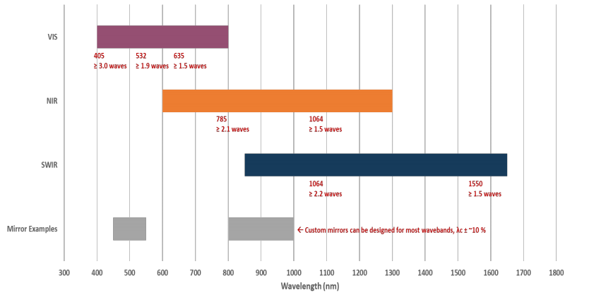
Laser 2000’s large format device the P1920 has three main wavebands that are determined by the liquid crystal (cell) thickness hence the optical path length and the AR coatings on the cover glass. These can be seen below:
Blazed gratings
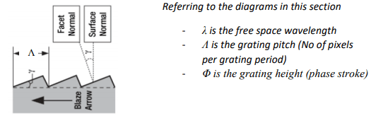
A blazed grating, known as Echelette grating is a specific form of reflective or transmission grating designed to produce the maximum grating efficiency in a specific diffraction order, minimising power in other orders. These blazed gratings have three main characteristics; the Blaze wavelength, the Blaze angle ϒ and the groove or facet spacing α.
A blazed phase grating is like a sawtooth profile where a 2PI phase shift is required and the diffraction efficiency depends on how well the SLM can depict the required phase ramp.
As number of digitised samples increase to infinity, 1st order diffraction efficiency tends to 100%. Typically, only 10 steps needed
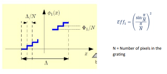
The phase modulation is dependent on the optical path length, wavelength/birefringence of the SLM and is normally fixed in the intervals of 0-2π radians by the LUT.
However, it is possible to ‘wrap’ (modulo 2π) the phase in adjacent pixels, with a discontinuous jump, such that a large amplitude arbitrary phase shape can be replicated.
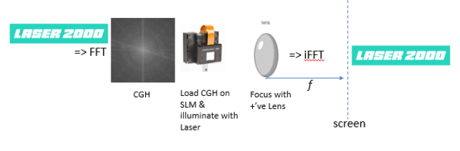
Computer-Generated Hologram (CGH)
The majority of SLM users us the interesting property of a lens which means that a simple lens can perform a Fourier Transform (FT) in real time. It is possible to form any function f(x) as a summation of a series of sine and cosine terms of increasing frequency.
In other words, any space or time varying data can be transformed into a different domain called frequency space. Given a set of sample data and a frequency the transform will give you the amplitude and phase of that frequency within the sample data.
Every point on the input image radiates an expanding cone of rays towards the lens (Huygens Principle), but since the image is at the focus of the lens, those rays will be refracted into a parallel beam that illuminates the entire image.
An optical FT automatically operates in the reverse direction also, where it performs an inverse FT converting the Fourier representation back into a spatial brightness image.
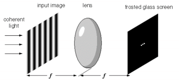
A Hologram is a recording of the light field i.e. contains amplitude and phase information. For Phase-only SLMs, the amplitude part of a complex field is discarded; therefore, the main function of the CGH computation algorithm is the transfer of object information from a complex field to the phase domain. The field reflected from the SLM carries the phase of a computer-generated hologram (CGH), therefore when the convergent beam reaches its waist, the Fourier transform of the hologram is reconstructed as an intensity field.
When trying to understand the efficiency of a CGH we need to see the Hologram (signal g) displayed on the SLM is a set of samples convolved with the rect function, which defines the shape of an individual pixel.
The Fourier Transform observed at the screen is composed of the central image (G), being an intensity FT of the input signal g and copies of the signal G due to the convolution of the comb function.
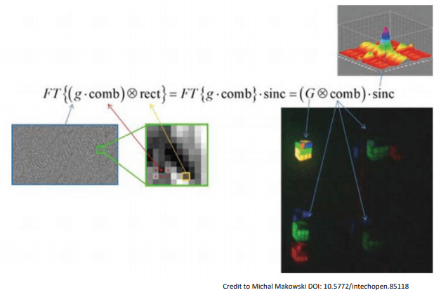
As mentioned previously with regards to ‘Fill Factor’ there is a presence of nonmodulating areas of the SLM due to the interpixel gap. The intensity pattern visible above is attenuated by the so-called intensity envelope, denoted by sinc, which in first approximation is the FT of the shape of an individual pixel.
Frame Rate
Laser 2000 offers the fastest Nematic SLMs on the market today with the capabilities for high frame rates over 1400 Hz, if you would like to find out more the product overview, it can be found on our category page Meadowlark SLM Range
‘Speed’ is a very misunderstood term but can be broken down into, Liquid Crystal Response time, computer-to-controller Transfer Time and controller-to-SLM Refresh Time. The Frame rate is the slowest combination of ALL three of these terms.
Many times, when the term ‘frame rate’ is used people are describing ‘transfer time’, ignoring the LC response and the refresh time, which impacts Phase Ripple. Also, many lower cost SLMs have emerged from display applications i.e. 60Hz refresh time.
Users should note that controllers that appear as a display or 2nd monitor in windows, such as DVI & HDMI have the tendency to drop frames to other processes because human eyes cannot detect these drops. PCIe does not have this problem with all frames arriving at the SLM.
- Liquid Crystal (LC) Response Time is a 10-90% measurement of the SLM switching through one wave of Phase Stroke. We quote the fall time (slower than rise time)
- Use 10/90% reference levels over a phase stroke of 2π (1 wave)
- Measure 1st-order diffraction spot, switch between blazed grating and blank hologram, grating is composite of many phase levels, closely mirroring most applications
- Measure at room temperature w/ low power laser, Response Time changes with λ and T
- Liquid Crystal (LC) Response Time is a 10-90% measurement of the SLM switching through one wave of Phase Stroke. We quote the fall time (slower than rise time)
- Computer-to-Controller Transfer Time – how fast can we get data onto the controller? Below are some of the typical specifications
- HDMI is 16.7 ms (60 Hz)
- PCIe is computer dependent, typically 660 μs (15 kHz) for 1920 SLM
- Computer-to-Controller Transfer Time – how fast can we get data onto the controller? Below are some of the typical specifications
- Controller-to-SLM Refresh Time
- SLM continuously refreshed by Controller
- Asynchronous to Transfer Time
- Cannot be interrupted, entire frame must load before changing data
- 1920 x 1120 is ~0.7 ms (1.436 kHz), 1024 x 1024 is ~0.7 ms (1.35 kHz)
- Controller-to-SLM Refresh Time
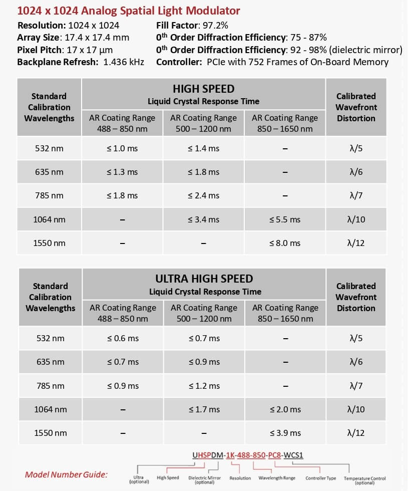
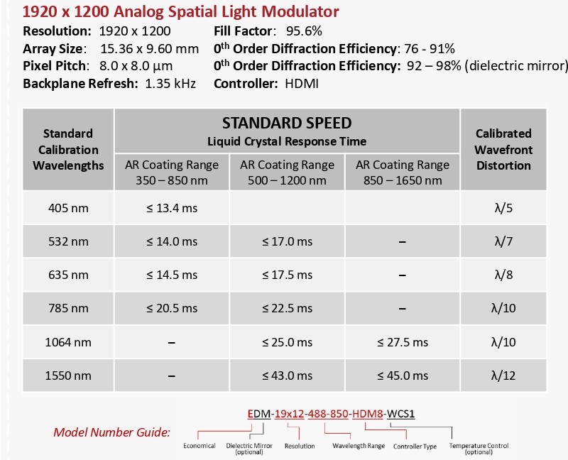
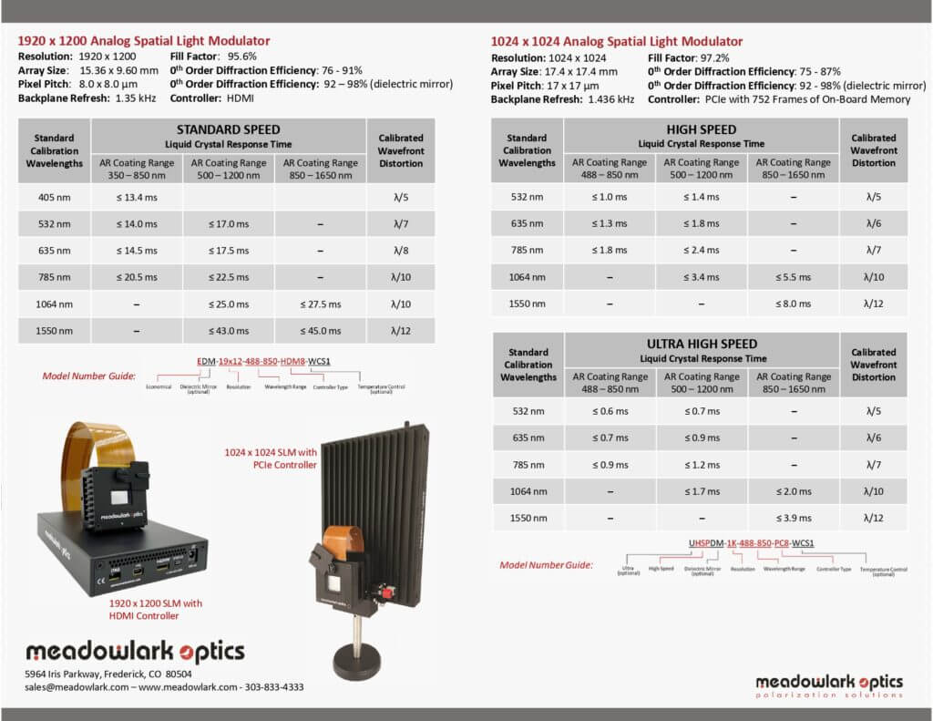
Below is an overview of the LC Response times for the various models:
Precision
Spatially varying phase response
In the non-modulating term, unevenness may arise due to the silicon backplane after the chemical mechanical polishing process, the surface flatness of the LC alignment layer or other components like the cover glass.
There are three main factors across the LCoS panel, when reviewing the modulating term. (1) the cell gap uniformity (2) the temperature effect on the panel (3) the voltage uniformity from the pixels.
After the native flatness of the panel the uniformity of the LC layer is the most important parameter affecting the output wavefront, requiring gap uniformity error of ~1% over the entire active area.
Laser 2000’s SLMs have high native flatness whilst employing electronic compensation, where the wavefront distortion value can be greatly enhanced from λ/5 to λ/12 (RMS).
Where the phase response varies over the SLM this can be termed ‘skew’.
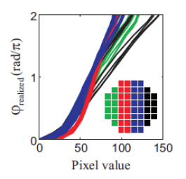
Measured phase response for 8×8 regions (each 64×64 pixels large) of an SLM as function of the addressed pixel value; the shape of φ realised as function of the pixel value varies over the SLM.
Time fluctuations/Phase flicker
All LC SLMs exhibit phase ripple, which varies with pixel voltage (phase value) which varies with temperature and wavelength.
Sources of phase ripple: • Polarity inversion of pixel voltages to maintain DC balance across LC • Common electrode not cantered • Refresh Time too slow, capacitors discharge.
Laser 2000’s backplanes are all analogue, as Pulse Width Modulation (PWM) used by digital backplanes to achieve intermediate phase level by a time-sequential voltage average cause phase ripple to vary rapidly and seemingly at random with pixel value.
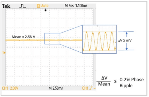
To measure, monitor the 1st-order diffraction spot with an oscilloscope and record the Peak-to-Peak (not RMS) using a blazed grating for wide variety of phase values. If the wavelength is 1 micron, then a phase ripple of 0.1% means phase stability of +/- 2nm.
Damage Mechanisms and limitations
In some cases, LCoS SLMs may be exposed to laser radiation that can cause permanent, irreparable damage to the SLM. The damage arises from several parameters and an in-depth review can be found here.
The main causes are from thermal damage, from high average power density CW and some nanosecond lasers and ablation damage from high peak power density lasers such as pico- or femtosecond lasers.
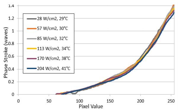
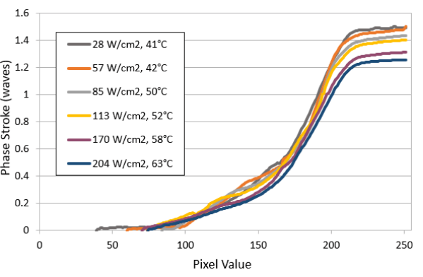
Thermal damage can be compensated using our optional liquid cooling system, but ablation damage cannot be compensated. The P1920 model can handle an average power at least 200W/cm2 and peak power densities at least 7.5GW/cm2 at 1035nm.
Graphs showing difference on phase stroke with and without cooling option.
4. Our recommendation on Meadowlark Optics
High Voltage Backplanes = Fastest Response Times Meadowlark Optics SLMs use custom backplanes, and proprietary drive schemes to achieve response times down to 0.5 ms (wavelength dependent). Most other liquid crystal spatial light modulators utilize display backplanes built with standard Nematic liquid crystal, limiting response time to >30 ms.
Highest Phase Stability Commercially Available Our backplanes are custom designed to allow high refresh rates up to (1.4 kHz), and direct analogue drive schemes. Refreshing the voltage at the pixel at rates far surpassing the response time of the liquid crystal ensures high temporal phase stability. Further, use of direct analogue drive schemes, as opposed to digital dithering, reduces optical flicker as low as 0.1% (0.001 π radians).
Low Inter-pixel Cross Talk Our backplanes are custom designed to offer high voltage at the pixel (5 – 10 V). Further, our SLMs are built with Meadowlark Optics proprietary liquid crystal which minimizes the required thickness of the LC layer in the SLM. By maximising the ratio of pixel pitch to LC thickness we are able to offer SLMs with minimal inter-pixel effects.
Broad Wavelength Capabilities Meadowlark Optics is the only SLM supplier capable of offering SLMs designed for use from UV (>365 nm) up to in the IR region (<1.7 µm).
Analogue is Better All Meadowlark SLMs have been designed for phase modulation. Unlike many display LCoS backplanes which require a pulse width modulation (PWM) scheme, Meadowlark backplanes utilize analogue voltages at each pixel. This results in a very stable phase response over time.
High Bit Depth Controllers Meadowlark offers 8 and 12-bit controllers to provide the most linear resolvable phase levels commercially available (up to 752). Fast transfer speeds from the computer to the SLM are offered up to 2 kHz.
Why don’t you try our high resolution, high speed HSP1920-1200nm model in your experiments today?
Contact us today :
used in a wide range of spatial light modulator applications including adaptive optics, STED microscopy, optical trapping, holographic beam shaping, and femtosecond pulse compression.