


Find out why Point Spread Functions means for biologists.
Written by our Biophotonics Team Leader PeterCollins.
In my last LinkedIn article ‘Nanoscopy for less than £100k?’ , information was provided on systems and modules that beat the diffraction limit, which means that the position of a single fluorophore can be located much more precisely than the ~200nm dictated by the diffraction limit. This limit prevents the detailed visualisation of key cellular structures: organelles (mitochondria, endosomes), cytoskeleton assemblies (actin, microtubules, intermediate filaments) and other scaffolding structures.
This article is the theoretical background to accompany ‘Nanoscopy for less than £100k?’
Written by Peter Collins
5-10 minutes Read
1. Single Molecule Localisation Microscopy (SMLM)
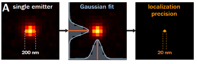
Single molecule localisation microscopy is a range of techniques based around the properties of a small set of fluorophores whose emission is temporally modulating or ‘blinking’. A single fluorophore emitter will appear as a ~200nm wide spot called the Point Spread Function (PSF). Due to the modulating nature of the emitters, the spatially isolated emission can have its position located well below the size of the PSF. This ‘blinking’ is acquired over a long sequence in order to localise millions of fluorophores, building up an image that has ~10X better resolution than a standard widefield microscope.
SMLM techniques are typically separated by the method used to achieve the effective ‘on-off’ switching of the fluorescence labels and not by the instrument hardware itself. These techniques are beyond the scope of this blog, but are broadly split into PALM and STORM references below:
1. Hess, S.T., Girirajan, T.P. and Mason, M.D., 2006. Ultra-high resolution imaging by fluorescence photoactivation localization microscopy. Biophysical journal, 91(11), pp.4258-4272.
2. Rust, M.J., Bates, M. and Zhuang, X., 2006. Sub-diffraction-limit imaging by stochastic optical reconstruction microscopy (STORM). Nature methods, 3(10), p.793.
2. Point Spread Function (PSF)
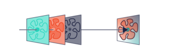
PSF, as the name suggests, is the response of an imaging system to a point source. This function describes the ‘spread’ due to the imperfect nature of the optical system. The final image is the convolution of the object with the PSF.
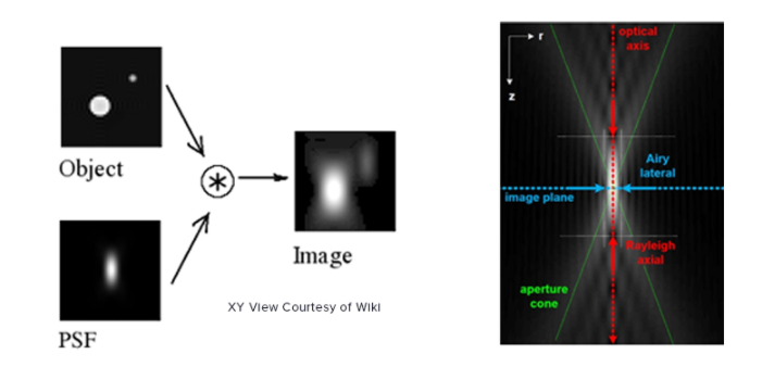
An optical system with resolution performance at the instruments theoretical limit is said to be diffraction-limited or Abbe Limit, which is proportional to the wavelength of light and the Numerical Aperture (NA). The NA can be thought of as the ability of a lens to collect light at oblique angles (n sinθ) and can be as high as 1.4 – 1.6. A nice rule of thumb is to half the wavelength, so around 200nm for visible light.
Resolution in microscopy has many different definitions but John William Strutt, 3rd Baron Rayleigh expanded on the work of George Airy and invented the ‘Rayleigh Criterion’ in 1896, which defines the diffracted limit as when the two point sources are distinguishable from each other. As mentioned above SMLM techniques can beat this criteria by temporally separating the two peaks and reporting on the peaks location, where the localisation precision is dependent on the photon flux. This can improve localisation precision to 8-20nm laterally, but what about axially?
3. Point Spread Function Engineering
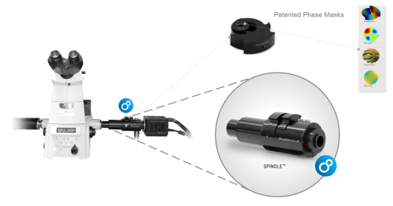
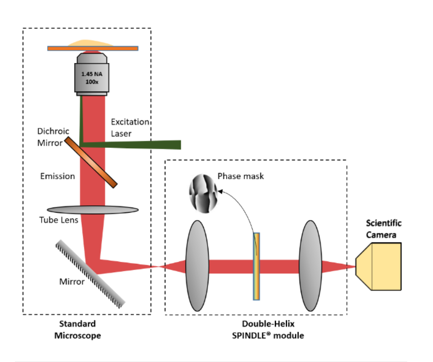
PSF Engineering can occur on both the excitation path, such as with STED microscopy or on the imaging path. Recent developments in SMLM have allowed the coordinate of an emitter along the axial direction, with a precision of 15 – 100nm. There are two major approaches; interferometry-based methods such as iPALM or PSF Engineering methods, such as astigmatism, double-helix and bi/multi-focal plane microscopy. The easiest way to accomplish this is by simply adding a cylindrical lens in the emission pathway, which introduces astigmatism to the image. Other techniques, whereby introducing phase masks into the pupil plane of the microscope, such as a Double Helix, which provides extended depth of field as can be seen in this video:
The Phase functions can be realised as surface relief patterns etched in glass, which means it can be inserted at the camera port of any microscope, by adding a 4f imaging arm and adding it to the Fourier plane. Most user facilities don’t like users tinkering with the microscope itself and therefore these modern techniques were left out from the mainstream. Our partner Double Helix Optics mission was to develop a product that was easy to use, align and could be added to most commercial microscopes, called the SPINDLE.
To help with the visualisation and 3D particle tracking, Double Helix Optics developed the 3DTRAX software.
Laser 2000 (UK) Ltd are delighted to represent Double Helix Optics in the UK & Ireland, and we have a demo SPINDLE that we can provide for demonstration or loan. To arrange a demo click contact us: