


It can be a confusing process selecting the best rotary stage from a list of specifications, some of which may not be important depending on the intended use. Zaber offers many different styles and sizes of motorised rotary stages, each well suited for particular applications. Here are the top things to consider when choosing the correct rotary stage:
- Installation Orientation – dictates how a rotary stage is installed and how subsequent loads must be supported.
- Load Capacity – generally determines how large a rotary stage is needed, higher capacity means a larger stage and more cost.
- Torque, Inertia and Angular Momentum – stages must accelerate, rotate and stop reliably while loaded, these factors help quantify the forces involved.
- Rotational Accuracy – imperfections exist in any mechanical system, determining the accuracy requirements for your specific application is critical.
- Mechanical Drive System – the design of the drive system has a direct impact on many of the above factors, especially max rotational speed.
Installation Orientation
Every application is different, and determining the required rotational axis orientation is the first step. Some applications that employ motorised rotary stages are optic positioning, 2 axis gimbals for scanning, sensor array testing and OEM assembly inspection, all may require vastly different mounting set-ups.
Installation orientation has an effect on many of the following selection parameters for rotary stages, with a significant impact on load capacity and the required drive torque to move a specified payload. Most commonly, a rotary stage is oriented so the rotational axis is:
- vertical (parallel to gravity)
- vertical but inverted (payload is suspended from stage)
- horizontal (perpendicular to gravity)
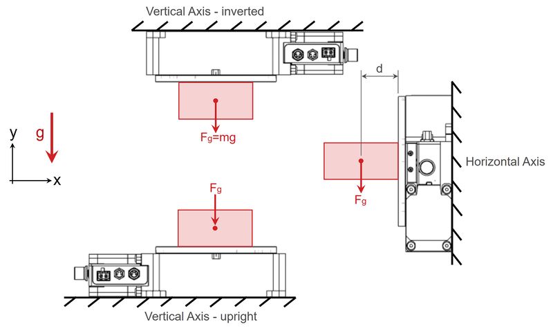
It is important to consider how each of these orientations changes the forces acting on the device.
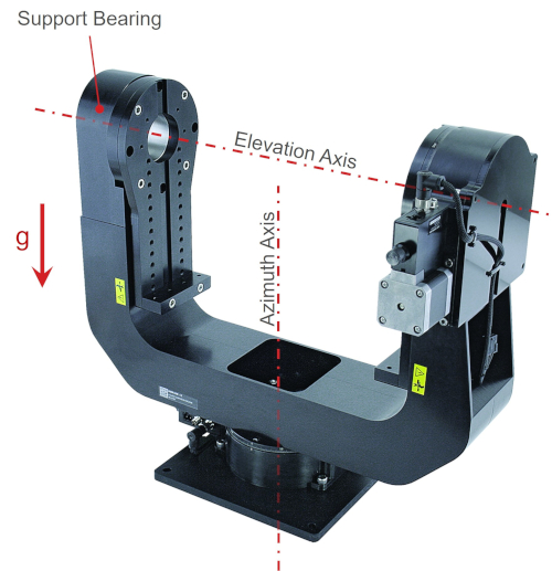
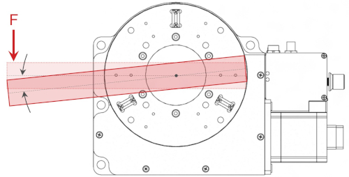
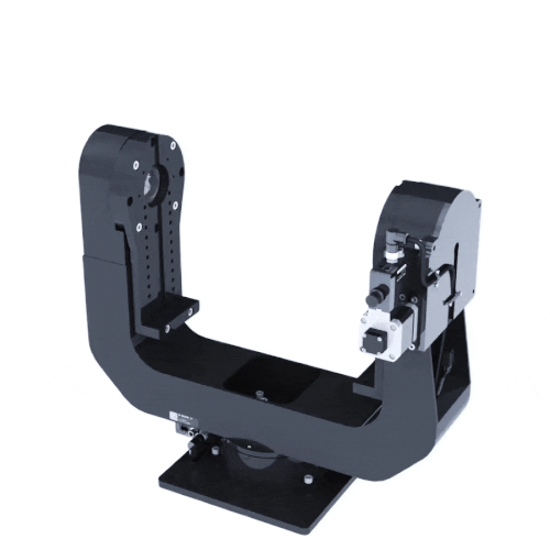
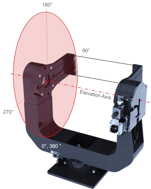
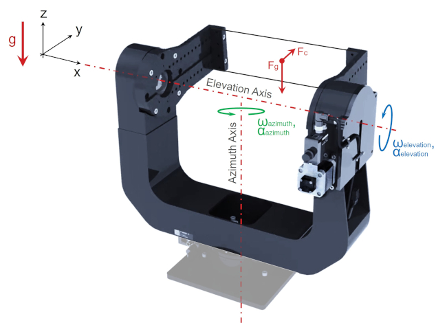
Let’s take a look at a 2 axis gimbal. Zaber’s X-G-RST300 gimbal below shows how the azimuth and elevation axes are oriented differently. The azimuth axis is vertical, and the elevation axis is horizontal. Despite both axes using the same X-RST120 rotary stage, the forces on each stage are completely different; a payload will induce axial forces on the azimuth axis and radial forces on the elevation axis. Cantilevered loads are also eliminated in the elevation axis stage by the addition of the secondary support bearing on the opposite side of the gimbal arm.
Axial and radial load capacity for rotary stages are not always equal. Installation orientation determines how we need to analyse the payload and resultant forces. A properly sized rotary stage will meet payload and lifetime requirements while being cost effective.
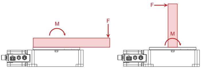
Free body diagrams (FBD) are a useful tool for laying out the forces that matter in your application. The diagram below shows X-RST120 rotary stages supporting a centred payload in the 3 most common orientations. In horizontal axis installations, the rotary stage will also need to support a cantilevered force, creating a moment on the stage top. The moment is: M = Fgd. This can be avoided by using a secondary bearing like in the gimbal shown above. The maximum cantilever load is listed for every rotary stage. Both the maximum centred load and maximum cantilever load needs to be considered in these instances.
On occasion, it is possible to have a rotary stage tilted, such that the rotational axis is not perfectly vertical or horizontal. In these cases, the force exerted by the payload mass must be simplified into component forces to determine the axial and radial load on the stage. This case is shown below.
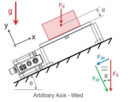
Looking at component forces that are parallel to the rotated xy coordinate axes, we see that Fgx must be considered as a radial load and Fgy must be considered as an axial load. From before, Fg = mg, and the component forces can be related by the angle of the rotational axis, θ. Again, it’s important to note that Fgx acts at the centre of mass, offset from the stage top by distance, d, and perpendicular to the rotational axis, thus creating a moment. The equations are shown below:
Fg = mg
Fgx = Fgsinθ = mgsinθ
Fgy = Fgcosθ = mgcosθ
Mθ = Fgxd = mgsinθd
(1)
(2)
(3)
(4)
Careful consideration is needed for applications requiring a horizontal rotation axis with long unsupported payloads. With cantilevered loads, the stage bearings need to fully support the radial load as well as the moment load, and any external axial loads from the application. For these applications, consider incorporating a secondary support bearing. For the best device lifetime and performance, it is recommended to operate below the maximum cantilever load and maximum centred load.
Load Capacity
The design of the drive train and the selection of the main bearings has the largest impact on load capacity. However, the load capacity of Zaber’s rotary stages are typically limited by motor torque. Most Zaber stages use oversized bearings which have been selected to enable larger aperture diameters. These bearings can withstand much greater loads than the motor can drive effectively.
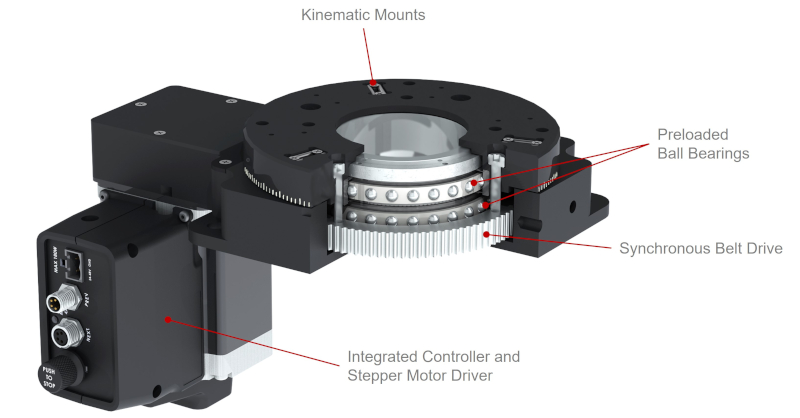
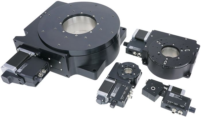
A collection of Zaber worm gear driven rotary stages are shown in figure 4. These have a wide range of load capacities from 5 kg to 300 kg and aperture diameters up to 101.6 mm or 4″. Regardless of other performance specs, as load capacity increases the price point generally increases.
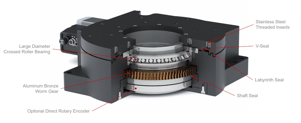
Most rotary stages use preloaded bearings, either ball bearings or crossed roller bearings. Crossed roller bearings offer excellent axial, radial and moment stiffness but generally cost more. Under high applied loads, less deflection occurs in systems with crossed roller bearings, and they are able to maintain more consistent and accurate motion. While crossed roller bearings provide the utmost performance, preloaded ball bearings are still an excellent choice for most applications. Despite being more compliant, they offer excellent accuracy and are highly cost effective.
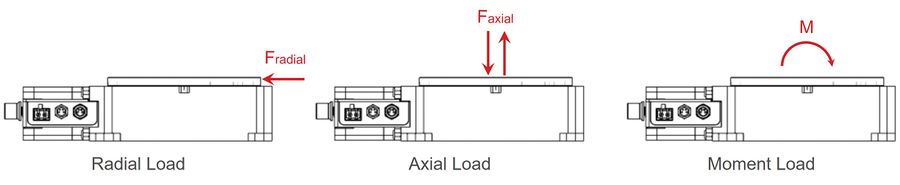
Bearings must support the applied radial loads, axial loads and moments throughout the lifetime of the rotary stage. The important loads and how they act on the rotary stage are shown in the figure 5 below.
Moment loads can also be the result of offset forces as shown in figure 6 below.
It is tempting to select an oversized rotary stage for maximum lifetime and load capacity. Be cautious however, as selecting an oversized stage when you may not need it can become very costly. Zaber’s load capacity specifications are an excellent guideline for most applications. One exception is for stiffness requirements; high accuracy applications can benefit from a small margin of extra capacity as deflections from applied loads will be minimised.
Another important aspect is torsional stiffness. Torsional stiffness defines the angular deflection of the rotary stage top about the rotational axis when the stage top is held static by the drive train, as shown in figure 7. This can be important in your application if the output needs to be held fixed during various processes when external loads are applied, such as indexing tables or robotic arm base joints. Worm gear driven rotary stages offer more torsional stiffness than belt driven stages.
Torque, Inertia and Angular Momentum
Rotational inertia of your payload has a direct impact on the torque required to accelerate your system and the size of the rotary stage. Torque is related to inertia and angular acceleration by Newton’s Second Law for Rotation:
τ = Iα
(5)
where,
- τ is torque [N⋅m]
- I is the moment of inertia [kg⋅m2]
- α is angular acceleration [rad/s2]
Zaber publishes detailed Torque Speed Performance plots for every rotary stage. These plots are critical in determining a range of speeds that a device can be used, and calculating the achievable acceleration based on the torque the device can exert.
For example, let’s examine the performance of a worm driven X-RST120AK-E03. Each payload will be a solid cylindrical disc with a diameter of 100 mm and with a mass, m of 15 kg. The payloads will be placed at increasing distances from the rotational axis. Assume the mounting plate has negligible mass and inertia.
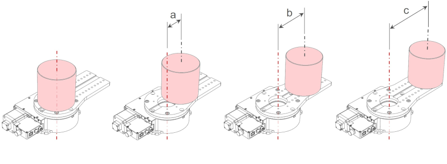
First, we should check if the offset payloads exceed the maximum cantilever load for the X-RST120 stage. With a payload of 15 kg and an offset of 150 mm, the load rating of 20 N⋅m is exceeded. However, we will continue with this example for educational purposes.
The inertia of an object is dependent on shape and mass distribution. Objects with identical mass can have completely different inertias. The moment of inertia, I, of a cylindrical disk rotated about its central axis is:
I = 0.5mr2
(6)
where,
- I is the moment of inertia [kg⋅m2]
- m is mass [kg]
- r is radius [m]
Moment of inertia formulas for other common shapes can be found here. Most computer-aided design (CAD) programs can also calculate inertia values.
In our example, the moment of inertia about the central axis is:
Icylinder, central axis = 0.5 x 15 kg x (0.05 m)2 = 0.01875 kg⋅m2
For the offset payloads, we can use the parallel axis theorem to calculate the moment of inertia. The parallel axis theorem for a body rotated about an axis that is not through its centre of mass is:
I = ICM + md2
(7)
where,
- I is the moment of inertia about the parallel rotational axis [kg⋅m2]
- ICM is the moment of inertia about the payload centre of mass [kg⋅m2]
- m is mass [kg]
- d is perpendicular distance between parallel axes [m]
The moments of inertia using the parallel axis theorem are:
- Ia = 50 mm = 0.01875 kg⋅m2 + 15 kg x (0.05 m)2 = 0.05625 kg⋅m2
- Ib = 100 mm = 0.01875 kg⋅m2 + 15 kg x (0.10 m)2 = 0.16875 kg⋅m2
- Ic = 150 mm = 0.01875 kg⋅m2 + 15 kg x (0.15 m)2 = 0.35625 kg⋅m2
The X-RST120AK-E03 has a listed maximum angular momentum spec of 0.4 kg⋅m2/s and a listed maximum speed of 24 °/s. If we want to rotate the various payloads at or below the maximum rated speed, we need to check that the system does not exceed the maximum rated angular momentum in operation. This is to ensure that the drive train can reliably withstand the impulse from a sudden stop (change in velocity). From Zaber’s testing we’ve found angular momentum is the best predictor of potential damage from a stall or emergency stop. To do this we need to determine the angular momentum, L, which is given by:
L = Iω
(8)
where,
- L is angular momentum [kg⋅m2/s]
- I is moment of inertia [kg⋅m2]
- ω is angular velocity [rad/s]
We can simply check the payload with the largest moment of inertia, that would be the payload with an offset of 150 mm. The inertia for this payload is Ic = 0.3563 kg⋅m2. At the maximum speed of 24 °/s or converting that to rad/s:
ω = 24 °/s x π/180 = 0.4189 rad/s
The largest angular momentum of our system would be:
L = Iω = 0.356 kg⋅m2 x 0.42 rad/s = 0.15 kg⋅m2/s
This is well below the maximum rated angular momentum for this rotary device.
To reliably accelerate, maintain a constant velocity at 24 °/s and controllably stop the payload, we need to calculate a maximum acceleration from data shown in Torque Speed Performance plot below.
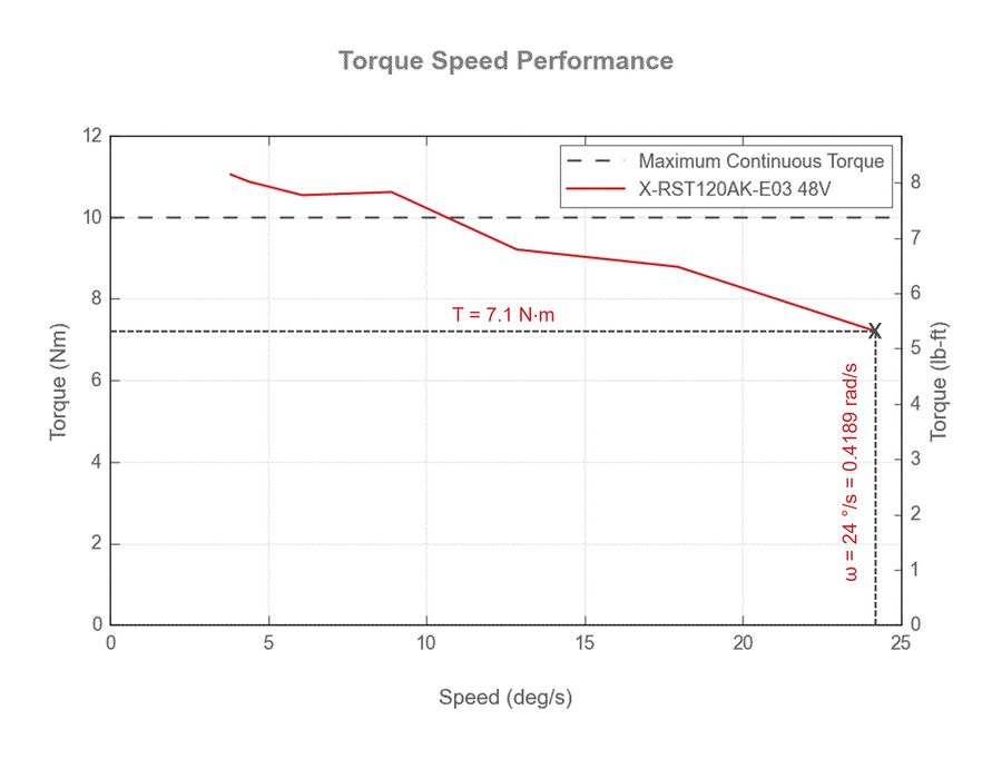
Examining figure 9, we see at 24 °/s, the peak torque output is approximately 7.1 N⋅m. From here we can calculate the maximum acceleration for this system:
α = τ/I = 7.1 N⋅m / 0.356 kg⋅m2 = 19.9 rad/s2 = 1142 °/s2
In reality, operating below this speed and acceleration will improve device lifetime and reliability, and is typically a worthwhile trade-off over absolute system speed and reduced positioning time. High accelerations, and frequent starts and stops, puts significant stress on the drive train. If this type of demanding motion is expected in your application, it may be advisable to select a larger and more powerful rotary stage.
Offset Loads in Gimbal Applications
Reviewing the X-G-RST300 gimbal shown earlier in figure 1, there is potential for the azimuth axis to be subjected to a large cantilevered load. This cantilevered load exerts a moment on the lower X-RST120 rotary stage. Additionally, the offset load also resists the driving force the elevation axis exerts to rotate the output stage. If the payload is incorrectly sized or offset by a large distance this can lead to the device stalling, excessive noise and increased wear.
The motion of a X-G-RST300 2 axis gimbal through its full travel range is shown in the animation below.
The largest cantilevered loads for the azimuth axis occur when a centred payload is rotated to 90° and 270°, as shown in figure 11 below.
A simple free body diagram of this application is shown in figure 12. The moment that the payload exerts on the lower azimuth axis X-RST120 is a function of the payload mass, m, and lateral offset, d. This payload simultaneously exerts a torque on the elevation axis, again a function of the mass and lateral offset.

In dynamic applications there can be acceleration forces and centrifugal forces. For example, if the elevation axis is accelerating the payload upwards through 90° and 270°, then the torque required to do so is even higher than the static holding torque, as equation 5 demonstrates. The axis must overcome the acceleration due to gravity and the opposing angular acceleration.
The dynamic torque applied to the elevation axis with angular acceleration is:
Tx, elevation, dynamic = Tg + Ta = mgd + Ielevationαelevation
(9)
where,
- T is torque [N⋅m]
- d is lateral offset [m]
The dynamic moment applied to the azimuth axis with non-zero angular velocity and acceleration is:
Mx, azimuth, dynamic = Fgd + Ta + Fch = mgd + Ielevationαelevation + mdωelevation2h
(10)
where,
- M is moment [N⋅m]
- d is lateral offset [m]
- Fc is centrifugal force [N]
- ωelevation is angular velocity of the elevation axis [rad/s]
- h is height from the azimuth axis stage top to the payload [m]. For the X-G-RST300, h = 0.275 m.
Equations 9 and 10 are useful to determine constraints on αelevation to avoid exceeding maximum torque and cantilever load capabilities of the stages. Rearranging and solving for αelevation gives the following two constraints:
αelevation ≤ (Tmax – mgd) / Ielevation
αelevation ≤ (Mmax – mgd – mdωmax2h) / Ielevation
(11)
(12)
where,
- Tmax is the maximum continuous torque listed in the spec table or determined from figure 9 at specific speeds [N⋅m]
- Mmax is the maximum cantilevered load listed in the spec table [N⋅m]
- ωmax is the maximum rotational speed listed in the spec table [rad/s]
For Zaber gimbal applications, the mdωmax2h term in constraint 12 can generally be ignored since the maximum rotational speed of worm gear driven rotary stages is low, causing this term to be negligible compared to the mgd term. However, for applications with a large height offset, h, or for belt driven rotary stages with higher speeds, it is worth including this term as it could be significant. As we continue with this example, we will ignore the term, essentially assuming the angular velocity, ω = 0 rad/s.
Generally for rotary stages the cantilevered load capacity Mmax will be higher than the allowable torque Tmax. Checking the spec table for these stages, we find this to be the case and we can therefore conclude that the angular acceleration αelevation will be limited by constraint 11 rather than constraint 12 since any angular acceleration that satisfies constraint 11 will also satisfy constraint 12.
So far we’ve considered the motion of the elevation axis and constraints on that motion imposed by the maximum torque spec Tmax and maximum cantilever load spec Mmax. Let’s now consider the motion of the azimuth axis. The structure driven by the azimuth axis stage is shown in figure 13. The maximum acceleration for the azimuth axis αazimuth will be limited by the following constraint:
αazimuth ≤ Tmax / Iazimuth
(13)
where,
- Iazimuth is the total moment of inertia about the azimuth axis including the payload and entire gimbal system [kg⋅m2]
Again, the inertia of an offset payload can be found using the parallel axis theorem:
Ielevation = ICM + md2
Iazimuth = Iazimuth, structure + ICM + md2
(14)
(15)
where,
- Iazimuth, structure is the moment of inertia of the gimbal structure, second rotary axis and support bearings but not the payload [kg⋅m2]
The value of Iazimuth, structure can be determined from an analysis of the 3D model using CAD software. Doing so we find that Iazimuth, structure = 0.25 kg⋅m2. For simplicity, we will consider the payload as a solid sphere with a mass of 4 kg and a radius of 0.075 m. The moment of inertia for a solid sphere is:
ICM, sphere = 2/5mr2 = 0.4mr2
(16)
Now that we’ve worked out all the formulas we can start plugging in numbers to determine whether this system meets the requirements of our application. We can also determine some constraints on our control of the system.
The moment of inertia for the payload mounted as shown in figure 12, at the worst case position of 90°, with an elevation offset, d, of 0.15 m is:
ICM, sphere = 0.4 x 4 kg x (0.075 m)2 = 0.009 kg⋅m2
Ielevation = ICM, sphere + md2 = 0.009 kg⋅m2 + 4 kg x (0.15 m)2 = 0.1 kg⋅m2
Iazimuth = Iazimuth, structure + ICM + md2 = 0.25 kg⋅m2 + 0.1 kg⋅m2 + 4 kg x (0.15 m)2 = 0.44 kg⋅m2
From constraint 11, and noting that the maximum full speed torque Tmax from figure 9 is 7.1 N⋅m, we can now calculate the maximum acceleration αelevation.
αelevation ≤ (Tmax – mgd) / Ielevation
αelevation ≤ (7.1 N⋅m – (4 kg x 9.81 m/s2 x 0.15 m)) / 0.1 kg⋅m2
αelevation ≤ 12 rad/s2
From constraint 13 we can calculate the maximum acceleration αazimuth.
αazimuth ≤ Tmax / Iazimuth
αazimuth ≤ 7.1 N⋅m / 0.44 kg⋅m2
αazimuth ≤ 16 rad/s2
The centred load acting on the azimuth axis stage is:
Fz, azimuth, centered = mg = 4 kg x 9.81 m/s2 = 39 N
Note that this reflects just the weight of the payload and not the weight of the gimbal structure. This is because we want to compare to the maximum centred load specification for the gimbal which already takes the weight of the gimbal structure into consideration.
The static moment acting on the azimuth axis due to gravity when at 90° or 270° is:
Mx, azimuth = 4 kg x 9.81 m/s2 x 0.15 m = 5.9 N⋅m
The torque required to rotate the elevation axis through a full rotation assuming no angular acceleration is:
Tx, elevation = 4 kg x 9.81 m/s2 x 0.15 m = 5.9 N⋅m
Reviewing the allowable loads from the X-G-RST300 specs, we find:
- Maximum Centered Load: 150 N
- Maximum Cantilevered Load: 20 N⋅m
Thus we can conclude that as long as angular accelerations are limited to the values indicated above a payload of this size and offset should be within the gimbal’s capabilities at all allowable speeds.
The resultant forces, torques and moments acting on the azimuth and elevation axes change as each rotary stage turns through its full 360° range so it is important to do the analysis at the worst case positions to determine if your application’s peak loads can be safely supported.
Rotary stages and gimbals can also support loads that are not centred, like in the example below.
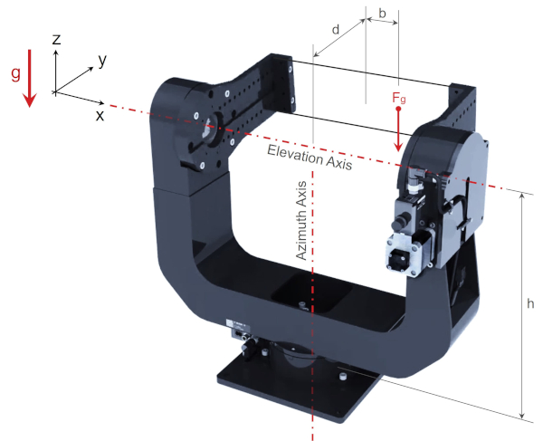
The analysis is more time consuming, but follows the same process shown above for determining the resultant forces, torques and moments. A key difference is that the azimuth axis must support a second moment caused by the non-centred offset, b. This additional moment acting on the azimuth axis persists regardless of the elevation axis position. The offset also shifts more of the radial load to the elevation axis rotary stage rather than the support bearing.
Rotational Accuracy
Just like any linear stage, rotary stages have slight imperfections and errors that can affect their quality and performance. Errors for rotary stages are typically defined differently than their linear counterparts. Rotational accuracy can be separated into two categories:
- Positioning accuracy: generally defined by accuracy, backlash and repeatability
- Axis of rotation accuracy: generally defined by radial error motion, axial error motion and tilt error motion
We will not go into great detail regarding rotational accuracy, other than helping define and illustrate the errors. If your application is highly sensitive to small errors, then it is worthwhile to investigate more thoroughly and contact our Applications Engineering team to help determine the correct rotary stage.
Positional Accuracy
Errors in the mechanical drive train of rotary stages lead to physical inaccuracies in angular positioning of the stage top.
Accuracy (unidirectional): is the maximum error possible when moving between any two positions, when both positions are approached from the same direction. Accuracy is measured in ° or mrad.
- Accuracy is influenced by the rotary drive mechanism and position feedback system.
- Typically one large error due to mounting eccentricity of the pulley or gear.
- Smaller periodic errors due to the drive train, such as worm shaft runout and belt tooth spacing.
- For the highest possible accuracy select rotary stages with direct encoders.
Backlash: is the maximum difference in the actual position possible when a target position is approached from opposite directions. Backlash is measured in ° or mrad.
- Backlash is present in belt drives and worm gear drives and occurs when the travel direction is reversed.
- High precision worm gear drives can operate with less backlash designed into the system than belt drives.
- For the lowest possible backlash select rotary stages with direct encoders.
Repeatability: is the maximum deviation in actual position when repeatedly instructing a device to move to a target position 100 times, approaching from the same direction every time, under stable thermal conditions. Repeatability is measured in ° or mrad.
- Repeatability is often confused with accuracy, but is typically more important for most applications. Make sure you know which spec you need.
Axis of Rotation Accuracy
Imperfections exist in any mechanical component or assembly. For rotary stages these imperfections can cause the theoretically perfect rotational axis to drift or tilt. These imperfections occur synchronously and asynchronously throughout a full revolution. These imperfections are referred to as error motion, and Zaber specifically measures radial, axial and tilt error motion.
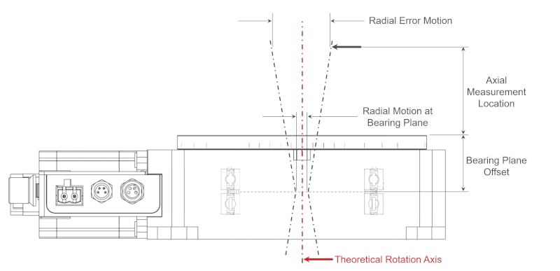
Radial Error Motion: is the deviation perpendicular to the mean axis of rotation, measured at a specified height above the bearing plane. This excludes stage top form errors. Radial error motion is typically measured in µm.
- Zaber measures the radial error at an axial location 50 mm above the stage top for RST and RSB120 series and 20 mm above the stage top for RSM, RSW and RSB060 series.
- This error is not what one might consider Runout or Eccentricity, which can be measured using a dial indicator and represents the variation in distance of a surface such as the rotary stage top from the mean axis of rotation. Rather the radial error motion represents radial movement of the axis of rotation itself.
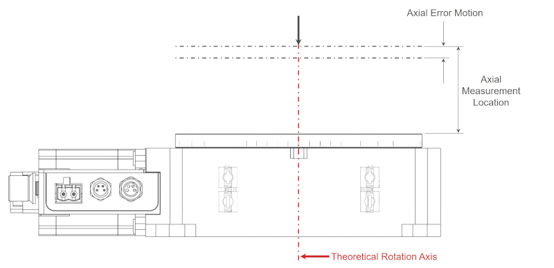
Axial Error Motion: is the linear deviation coaxial to the mean axis of rotation. This excludes stage top form errors. Axial error motion is typically measured in µm.
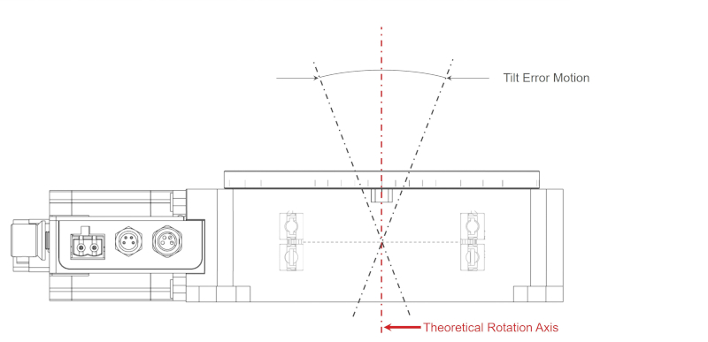
Tilt Error Motion: is the angular deviation of the axis of rotation away from its mean position. This excludes errors from stage base parallelism, and stage top parallelism. Tilt error motion is measured in angular units, commonly ° or µrad.
Bearing Plane Offset: is the distance from the bearing plane (mid-plane) to the surface of the stage top. The bearing plane offset is shown in figure 15 and is listed in the specs table for every rotary stage. The two measurement configurations depending on the size of stage are:
- 50 mm + Bearing Plane Offset (RST, RSB120)
- 20 mm + Bearing Plane Offset (RSM, RSW, RSB060)
Mechanical Drive System
There are many ways to transmit motor rotation to the stage top. Two of the most common methods are worm gears and belt drives. Zaber offers both styles of devices, each with their own strengths and drawbacks.
The key questions to ask yourself when selecting a rotary drive mechanism are:
- Do you require high speed rotation? Belt driven stages are typically much faster than gear driven stages. While the max speed of Zaber’s gear driven stages ranges from 4-75 RPM, our belt driven stages can easily reach 600 RPM.
- Are you okay with a back-drivable axis in the event of power loss? In the event of power loss it is possible for belt driven stages, and low reduction worm drives (about <50:1) to back drive due to the payload. This can be a safety concern depending on the application and may even result in damage to sensitive equipment mounted to the device. Brakes or additional gear reducers can be used to mitigate this problem.
- Do you require the highest possible positioning accuracy? Precision worm gear drives excel here, especially devices equipped with direct reading rotary encoders.
- Is backlash critical in your application? Both systems have backlash, however the backlash of precision worm drives is typically less than belt drives.
- Does your application require high torque for moving a large off-axis payload or accelerating quickly? A large reduction worm drive can be packaged in a smaller device volume and deliver more torque than a similarly sized belt drive. Higher output torques enable faster acceleration for medium to large payloads.
Worm Gear Drives
Pros:
- Large gear reduction
- High load capacity
- Good torsional stiffness
Cons:
- Cost
- Mechanical friction & heat generation
- Wear
Belt Drives
Pros:
- Cheap
- Low noise
- High speed
Cons:
- Low stiffness
- Back-drivable
- Backlash