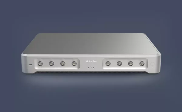


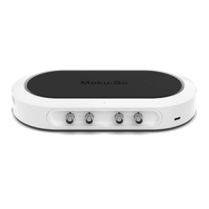
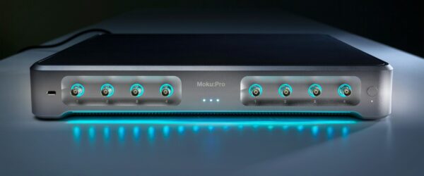
Moku:Pro – The most powerful platform for your research and engineering applications
-
- Performance and flexibility
- Multiple instruments in one integrated platform – use up to four at once!
- Future-proof your lab with the reconfigurable FPGA
- Ultimate lab freedom
Liquid Instruments’ Moku:Pro is leading the next generation of software-defined instrumentation by harnessing the power of an FPGA and coupling it with a high-quality analog front-end. This allows Moku:Pro to have the flexibility of hosting multiple instruments without having to compromise on specifications or precision.
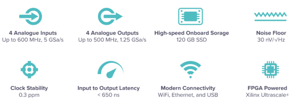
It can monitor up to 5 GSa/s with industry-leading noise performance and offers eleven different instruments which can be used separately or chained together to make a signal processing pipeline or reconfigurable test systems.
Instrumentation:
Moku:Pro comes with five essential instruments included on the base model. You can then add other high-performance instruments, either from purchase (“build-your-own” model) or as add-ons after purchase (as an upgrade) to personalise Moku:Pro and enhance its’ capability.
The five essential instruments that come with every Moku:Pro are:

The other instruments that come with the “Full-suite” bundle, or that can be purchased at any time and installed onto the hardware with the upgrade option are:

Having a Moku:Pro for your experiments means you can keep one hardware platform and reconfigure the software to suit the project you are undertaking. Replacing multiple pieces of equipment with one device will dramatically reduce the cost of your lab, allowing you to “measure more with less” whilst future-proofing your lab at the same time.
More information about the instruments available for Moku:Pro can be found through this link.
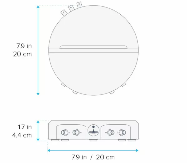
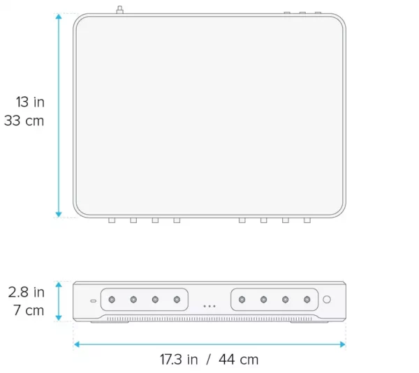
Specification Overview:
Please find the series specs tab for more detail on the specifications.
Key Features:
Multi-instrument Mode
Use four instruments simultaneously to build custom signal processing pipelines or sophisticated test systems. Moku:Pro is reconfigurable allowing you to swap which instruments you are using with ease to allow a deeper understanding into your projects and the relationships between instruments.
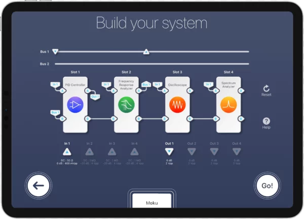
Signals between instruments can be routed through Digital Signal Buses, enabling high data rates with ultra-low latency and no degradation of SNR, that typically would result from the analog-to-digital or digital-to-analog conversions in separate hardware modules or boxes. Having all the required instruments available in one hardware platform can also substantially decrease research and development time.
Moku Cloud Compile
A cloud-based tool which allows you to implement custom triggering or digital signal processing with your own VHDL code. It is compatible with multi-instrument mode, meaning your coded solutions seamlessly integrate into the intuitive UI and pre-existing Moku instruments, which makes implementation a simple task.
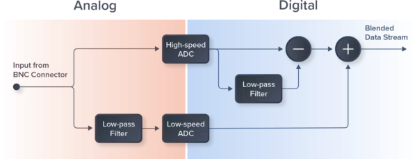
Blended ADCs
Liquid Instruments has overcome the typically demanded tradeoffs between flexibility and performance by blending two ADCs. As Moku:Pro has a wide range of available instruments, it needs to perform in lots of different measurement scenarios, but this means a single ADC cannot be optimised. Having a non-optimised ADC normally introduces a noise error to the signal however Liquid Instruments has mitigated this by using a patented blending scheme. By using signals from a 5 GSa/s, 10-bit ADC and a 10 MSa/s, 18-bit ADC, they are able to deliver a low noise floor and a high dynamic range.
This blended ADC technology means engineers and researchers no longer need to compromise between high speed and high precision when acquiring data.
Differential features:
Lab Freedom
Moku:Pro is perfectly paired with an iPad which can be used to control experiments through the free app. Having a portable display and experimental controller allows you to take data from anywhere and to have ultimate freedom in your lab. Moku:Pro can also be controlled by Windows and Mac apps along with having API support for Python, MATLAB, and LabVIEW.
Digital Twin – Model and Emulate Subsystems
Product models are usually built before the physical hardware is available, therefore these models cannot be run until late in the development cycle. With Moku:Pro, customers can run and test their models to find and correct problems earlier in the cycle, lowering the number of engineering change requests and decreasing the amount of time to market. The same code can then be deployed onto the embedded system once it has been made.
Obsolescence Planning
Products with long product life cycles can outlast the test equipment used to validate and produce them. With Moku:Pro, instruments at End of Life (EOL) can be recreated as software modules allowing for faster and easier integration. Moku:Pro and Moku Cloud Compile can be used to recreate the EOL instruments, saving time compared to recreating a large testing system.
Below is short video from Liquid Instruments highlighting the features of Moku:Pro: