Multiple Z-plane XYZΘΦ Scanning Slit System, 190 to 2500* nm
Port-powered USB 2.0
Features
- 190 to 1150 nm, Silicon detector
- 650 to 1800 nm, InGaAs detector
- 1000 to 2300 or 2500 nm, InGaAs (extended) detector
- Port-powered USB 2.0; flexible 3 m cable; no power brick
- 0.1 µm sampling and resolution
- Linear & log X-Y profiles, centroid
- Profile zoom & slit width compensation
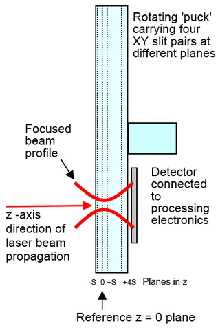
- Real-time multiple Z plane scanning slit system
- Real-time XYZ profiles, Focus position
- Real-time M2, Divergence, Collimation, Alignment
Applications
- Laser printing & marking
- Medical lasers
- Diode laser systems
- Fibre optic telecom assembly focusing –
LensPlate2™ option for re-imaging waveguides and fibre ends - Development, production, field service
- CW; Pulsed lasers, Φ µm ≥ [500/(PRR in kHz)]
- M2 measurement with available M2DU stage
| Wavelength | Si detector: 190 to 1150 nm
InGaAs detector: 650 to 1800 nm
Si + InGaAs detectors: 190 to 1800 nm
Si + InGaAs (extended) detectors: 190 to 2300 or 2500 nm |
| Scanned Beam Diameters | Si detector: 5 µm to 4 mm, to 2 µm in Knife-Edge mode*
InGaAs detector: 10 µm to 3 mm, to 2 µm in Knife-Edge mode*
InGaAs (extended) detector: 10 µm to 2 mm, to 2 µm in Knife-Edge mode* |
| Beam Waist Diameter Measurement | Second moment (4s) diameter to ISO 11146; Fitted Gaussian & TopHat
1/e2 (13.5%) width
User selectable % of peak
Knife-Edge mode* for very small beams |
| Beam Waist Position Measurement | ± 20 µm best in X, Y, and Z — contact DataRay for recommendation |
| Measured Sources | CW; Pulsed lasers, Φ µm ≥ [500/(PRR in kHz)] |
| Resolution Accuracy | 0.1 µm or 0.05% of scan range
± < 2% ± = 0.5 µm |
| M2 Measurement | 1 to > 20, ± 5% |
| Divergence/Collimation, Pointing | 1 mrad best — contact Laser 2000 for recommendation |
| Maximum Power & Irradiance | 1 W Total & 0.5 mW/µm2 |
| Gain Range | 1,000:1 Switched 4,096:1 ADC range |
| Displayed Graphics | X-Y-Z Position & Profiles, Zoom x1 to x16 |
| Update Rate | ~5 Hz |
| Pass/Fail Display | On-screen selectable Pass/Fail colors. Ideal for QA & Production. |
| Averaging | User selectable running average (1 to 8 samples) |
| Statistics | Min., Max., Mean, Standard Deviation
Log data over extended periods |
| XY Profile & Centroid | Beam Wander display and logging |
| Minimum PC Requirements | Windows, 2 GB RAM, USB 2.0/3.0 port |
* Knife-Edge mode requires 3XYKE or CM3 model