Laser 2000

Photon Timing PicoHarp 300

PicoHarp 300

The PicoHarp 300 is a high-end, easy to use, plug and play Time-Correlated Single Photon Counting (TCSPC) system. It is connected to a PC through a USB 2.0 interface.

PicoQuant Logo

The PicoHarp 300 is a high-end, easy to use, plug and play Time-Correlated Single Photon Counting (TCSPC) system. It is connected to a PC through a USB 2.0 interface. The high quality and reliability of the PicoHarp 300 is expressed by a unique 5-year limited warranty.

Independent channels, 4 ps resolution

A special design approach provides identical and synchronized but independent input channels. They can be used as detector inputs for coincidence correlation experiments or as a pair of start and stop inputs for TCSPC. It allows a forward start-stop operation even at full repetition rate of mode locked lasers with stable repetition rate up to 84 MHz. Experiments with low repetition rate benefit from the PicoHarp’s multi-stop capability. The design allows high measurement rates up to 10 million counts/sec and provides a highly stable, crystal calibrated time resolution of 4 ps. The instrument’s timing resolution is well matched to even the fastest detectors currently available: the SPAD detectors of the PDM series or micro-channel plate Photomultiplier Tubes (MCP). Both input channels are equipped with Constant Fraction Discriminators (CFD), sensitive on the falling edge.

Adjustable delay in sync channel

The sync channel of the PicoHarp 300 even has an internal adjustable delay with ±100 ns range at 4 ps resolution. This unique feature eliminates the need for specially adapted cable lengths or cable delays for different experimental set-ups.

Operation as time tagger

PicoHarp 300 - Screenshot of the online correlator

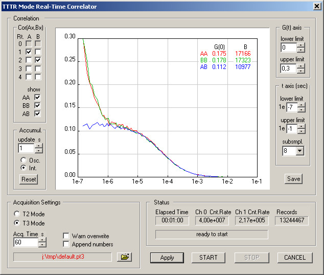
A Time-tagged mode for recording of individual photon events with their arrival time on both channels is available as an option, allowing the most sophisticated offline analysis of the photon dynamics. TTTR data can be correlated in real-time for monitoring of FCS experiments at count rates up to 500 000 counts/sec. External marker signals can be used to synchronize the device with other hardware such as scanners, e.g., for Fluorescence Lifetime Imaging (FLIM). In TTTR mode, the PicoHarp 300 can also be used as a generic event timer, e.g., for Satellite Laser Ranging (SLR).

Multichannel routing

As accessories external routers such as the PHR 800 for connection of up to four detectors are available. Each router channel includes an internal adjustable delay with ±8 ns range at 4 ps resolution to tune for relative delays. External hardware such as monochromators can be controlled via CAN or serial bus (currently supported: Sciencetech 9030, Sciencetech 9055, Acton Research SP-2155 and Acton Research SP-275).

Measurement channels
Discrimination Constant Fraction Discriminator (CFD) in both channels, software adjustable
Input voltage range 0 to -800 mV, optimum: -200 mV to -400 mV
Trigger point falling edge
Trigger pulse width 0.5 ns to 30 ns
Trigger pulse rise/fall time 2 ns max.
Time to Digital Converter (TDC)
Minimum time bin width 4 ps
Timing precision* < 12 ps rms
Timing precision / √2* < 8.5 ps rms
Adjustable delay range for sync channel ± 100 ns, resolution 4 ps
Full scale range – histogram mode 260 ns to 33 μs (depending on chosen resolution: 4, 8, 16, …, 512 ps)
Full scale range – time-tagged mode infinite
Maximum count rate 10×106 counts/sec
Maximum sync rate 84 MHz
Dead time < 95 ns
Differential non-linearity < 5 % peak, < 1 % rms
Histogrammer
Count depth 16 bit
Maximum number of time bins 65 536
Acquisition time 1 ms to 100 hours
TTTR engine
T2 mode resolution 4 ps
T3 mode resolution 4, 8, 16, …, 512 ps
FiFo buffer depth (records) 262 144
Sustained throughput** typ. 5×10⁶ events/sec
Operation
PC interface USB 2.0 high speed
PC requirements min. 1 GHz CPU clock, 512 MB memory
Operating system WindowsTM 7 / 8  (8.1) / 10
Power consumption 25 W at 100 to 240 VAC

* In order to determine the timing precision it is necessary to repeatedly measure a time difference and to calculate the standard deviation (rms error) of these measurements. This is done by splitting an electrical signal from a pulse generator and feeding the two signals each to a separate input channel. The differences of the measured pulse arrival times are calculated along with the corresponding standard deviation. This latter value is the rms jitter which we use to specify the timing precision. However, calculating such a time difference requires two time measurements. Therefore, following from error propagation laws, the single channel rms error is obtained by dividing the previously calculated standard deviation by √2. We also specify this single channel rms error here for comparison with other products.

**Sustained throughput depends on configuration and performance of host PC.

Datasheet
Technical Notes
BACK
TO TOP

Request a Demo

PicoHarp 300

Ask the Expert

If you’re interested in the products shown here, or have questions about something you can’t find on our website, please get in touch through the form below.

Our knowledgeable sales team will be happy to help. We can normally source exactly what you need, or work with you to come up with custom solutions.

Alternatively, just call +44 (0) 1933 461 666 and ask to speak to the Photonics team.