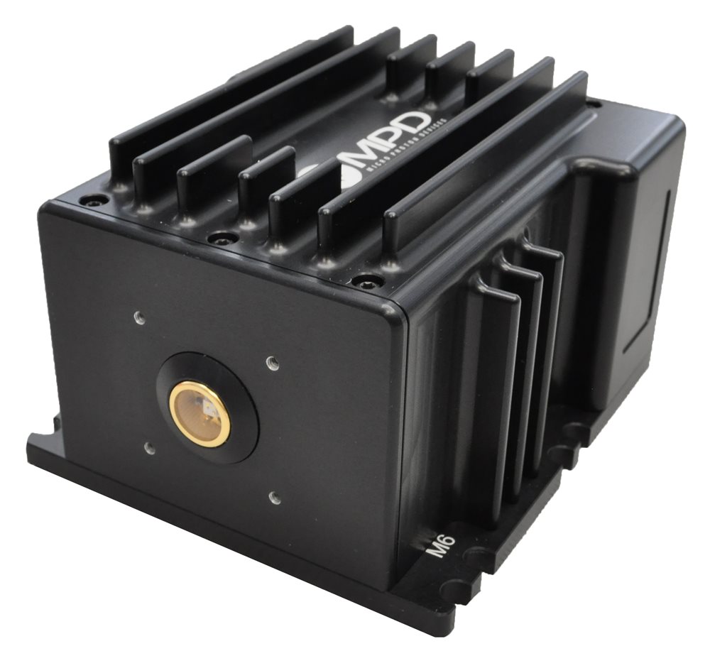
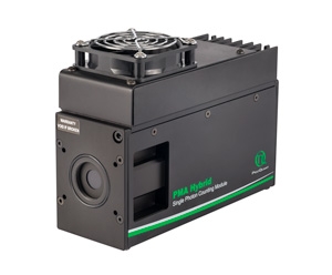
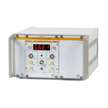
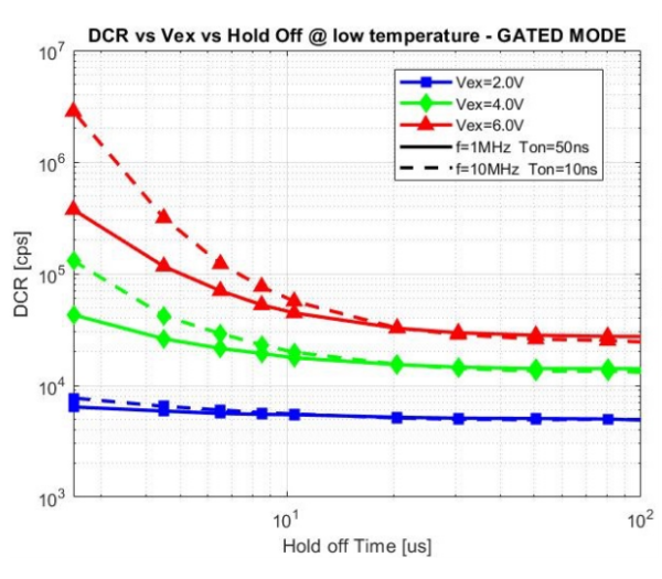
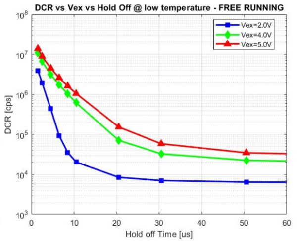
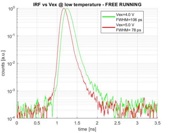
The PDM-IR is a photon counting module based on an InGaAs/InP Single-Photon Avalanche Diode (SPAD) for the detection of near-infrared single photons up to 1700 nm (see PDE graphs). The module includes a programmable frequency and pulse generator for gating the detector, a front-end circuit for photodetector’s avalanche sensing, a fast circuit for detector’s avalanche current quenching and operative bias voltage resetting and some sub-circuits for signal conditioning. All the main parameters and delay paths are adjustable by the user through the software interface, in order to match the requirements of different applications. The system can be conveniently used both for counting and timing measurements, since the high-performance electronics guarantees a clean temporal response even with fast gate transitions (see typical IRF curves displayed here below). PDM-IR can work either in free-running or in gated mode and the optical interface can be chosen between free space and a pigtailed version. Here below typical DCR vs Hold-Off are shown for both gated and free-running modes.
System requirements (software and SDK):
- The host computer (minimum requirements): USB 2.0 interface, 1 GHz processor and 512 MB of RAM
- Supported operating systems
- VisualPDM-IR
- Microsoft 7, 8,10, 32- or 64-bit versions
SDK:
- Microsoft 7, 8,10, 32- or 64-bit versions
- Linux Ubuntu 12.04 LTS, Fedora Core 15 or compatible distributions, 32- or 64-bit versions
- Mac OS X 10.7.5 and above
Freespace
| Parameter |
Notes |
Min |
Typ |
Max |
Units |
| SPAD Active Area Diameter |
|
|
25 |
|
µm |
| Photon Detection Efficiency |
Vex = 7V, λ=1550 nm |
|
32 |
|
% |
| Timing Jitter (FWHM) |
At VEX = 4 V (all working modes) |
100 |
130 |
|
ps |
| At VEX = 7 V (Fixed Gate mode only) |
|
60 |
|
ps |
| Minimum Wavelength for IRF with SHORT TAIL |
Below 975 nm photons are absorbed in the top InP layer only |
|
975 |
|
nm |
| DCR (dark counting rate) |
At VEX = 2 V, Temperature set to “Low”, module in free running mode, hold-off time = 100 µs |
|
5 |
10 |
kcps |
| SPAD Temperature |
SW Selectable |
225 |
|
243 |
K |
| Gate Rise Time |
(20% – 80%) |
|
2 |
|
ns |
| Excess Bias Range |
Free Gate and Free Running |
2 |
|
5 |
V |
| Fixed Gate |
2 |
|
7 |
V |
| Hold-off Time |
SW selectable @ 10 ns step |
1 |
|
3000 |
µs |
| Gate Width |
SW selectable @ 1 ns step |
1 n |
|
1.5 m |
s |
| Gate Repetition Frequency |
|
|
|
100 |
MHz |
| Internal Trigger Frequency |
SW selectable @ 1 Hz step |
100 |
|
100 M |
Hz |
| Delay path |
SW selectable @ 1 ns step |
0 |
|
100 |
ns |
| Counter Integration Time |
SW selectable @ 20 ms step |
0.1 |
|
60 |
s |
| PHOTON OUT, NIM OUT |
NIM output |
-800 |
|
0 |
mV |
| Required Load (DC) |
|
50 |
|
Ω |
| PHOTON OUT |
Pulse width |
|
10 |
|
ns |
| TRIGGER IN, AUX IN |
Amplitude |
-2 |
|
2.5 |
V |
| Load Impedance (DC) |
|
50 |
|
Ω |
| Pulse width |
800 |
|
|
ps |
| TTL OUT |
Output levels |
0 |
|
2.7 |
V |
| Required Load (DC) |
|
50 |
|
Ω |
| Power Supply |
Power |
|
|
15 |
VA |
| DC INPUT Voltage |
11.4 |
12 |
12.6 |
V |
| Operating range |
Ambient temperature |
15 |
|
35 |
°C |
Fibre Pigtailed
| Parameter |
Notes |
Min |
Typ |
Max |
Units |
| Fibre Pigtail Type |
FC/PC – uses 10 µm SPAD |
SMF-28 |
|
| FC/PC – uses 25 µm SPAD |
MMF 50 µm GI NA=0.2 |
|
| Photon Detection Efficiency |
Vex = 7V, λ=1550 nm |
|
25 |
|
% |
| Timing Jitter (FWHM) |
At VEX = 4 V (all working modes) |
90 |
130 |
|
ps |
| At VEX = 7 V (Fixed Gate mode only) |
50 |
70 |
|
ps |
| Minimum Wavelength for IRF with SHORT TAIL |
Below 975 nm photons are absorbed in the top InP layer only |
|
975 |
|
nm |
| DCR (dark counting rate) |
At VEX = 2 V, Temperature set to “Low”, module in free running mode, hold-off time = 100 µs |
SMF-28 |
|
0.5 |
1 |
kcps |
| MMF-50GI |
|
2.6 |
5 |
kcps |
| SPAD Temperature |
SW Selectable |
225 |
|
243 |
K |
| Gate Rise Time |
(20% – 80%) |
|
2 |
|
ns |
| Excess Bias Range |
Free Gate and Free Running |
2 |
|
5 |
V |
| Fixed Gate |
2 |
|
7 |
V |
| Hold-off Time |
SW selectable @ 10 ns step |
1 |
|
3000 |
µs |
| Gate Width |
SW selectable @ 1 ns step |
1 n |
|
1.5 m |
s |
| Gate Repetition Frequency |
|
|
|
100 |
MHz |
| Internal Trigger Frequency |
SW selectable @ 1 Hz step |
100 |
|
100 M |
Hz |
| Delay Path |
SW selectable @ 1 ns step |
0 |
|
100 |
ns |
| Counter Integration Time |
SW selectable @ 20 ms step |
0.1 |
|
60 |
s |
| PHOTON OUT, NIM OUT |
NIM output |
-800 |
|
0 |
mV |
| Required Load (DC) |
|
50 |
|
Ω |
| PHOTON OUT |
Pulse width |
|
10 |
|
ns |
| TRIGGER IN, AUX IN |
Amplitude |
-2 |
|
2.5 |
V |
| Load Impedance (DC) |
|
50 |
|
Ω |
| Pulse width |
800 |
|
|
ps |
| TTL OUT |
Output levels |
0 |
|
2.7 |
V |
| Required Load (DC) |
|
50 |
|
Ω |
| Power Supply |
Power |
|
|
60 |
VA |
| DC INPUT Voltage |
22.8 |
24 |
25.2 |
V |
| Operating Range |
Ambient temperature |
15 |
|
35 |
°C |
1See the user-manual for the full list of module’s specifications. Module designed and built compliant with the European Union Directive 2011/65/CE (also known as RoHS 2).


