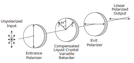
The LVA offers real‐time, continuous control of light intensity. Our attenuator consists of an LC Variable Retarder (with attached compensator) operating between crossed linear polarisers.
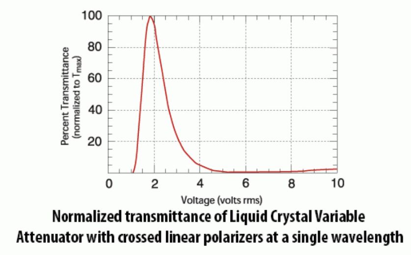
With crossed polarisers, light transmission is maximized by applying the correct voltage to achieve half‐wave retardance from the LC cell. Half‐wave operation rotates the incoming polarisation direction by 90°, so that light is passed by the second polariser. Minimum transmission is obtained with the retarder operating at zero (or a whole number of) waves.
Transmission decreases as the applied AC voltage amplitude increases (half‐ to zero‐waves retardance). The relationship between transmittance T and retardance (in degrees) for crossed polariser configuration is given
by: T(Θ) = 1/2 [1 ‐ cos(Θ)] Tmax
where Tmax is the maximum transmittance
when retardance is exactly one‐half wave (or 180°).
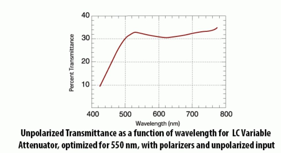
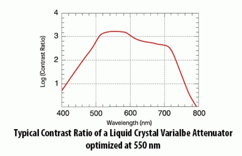
A Liquid Crystal Variable Attenuator can be configured with high efficiency calcite or beamsplitting polarisers to maximize light transmittance and increase damage threshold. With a linearly polarised input beam and a calcite polariser, transmittance values exceed 90% at most wavelengths. Very high contrast ratios, in excess of 5000:1, can be achieved with custom double attenuators. In this design, two Liquid Crystal Variable Retarders are combined with three polarisers.
Custom devices for near infrared applications, utilizing appropriate dichroic polarisers, can also be manufactured.


