


In this blog, we discuss the current guide for all optosigma manual stages, from testing environments, guide structure, operation diagrams and definitions of terminology and specifications.
Operating Environment of Manual Stages
Use manual positioning stages within the following environment temperature range. Contact us for information regarding using the stages outside the given operational environment temperature range.
Operating environment.
Stainless steel manual stages −20°C 〜 +120°C
Stages with digital micrometer head 0°C 〜 +40°C
Other manual stages −20°C 〜 +70°C
Recommended Environment: 23°±5°C, 60±10% (without condensation)
Operating environment temperature changes depending on various conditions such as the type of positioning stage, installation and operation conditions.
Avoid use of the stages in the following sites
- Sites subject to water or oil
- Sites subject to direct sunlight or radiant heat
- Sites subject to dirt and dust
- Sites subject to vibration or impact
- Sites close to fire
- Sites subject to inflammable gas and corrosive gas
Installation Direction (Mounting)
The values in the specifications of each product are based on installation on a horizontal surface.
Note that load capacity and other specifications will significantly change for upside down, lateral horizontal and other
installation orientations.
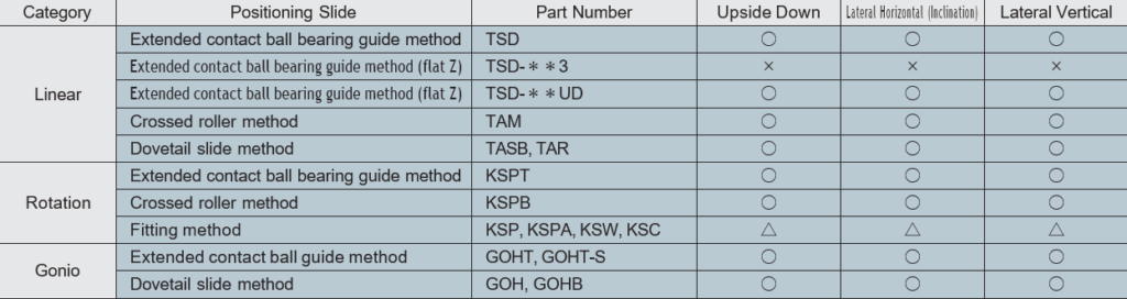
○: Possible with limits on load and moment, etc.
△: May significantly deteriorate precision depending on installation orientation, but possible with limits on load and moment, etc.
×: Not allowed
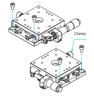
Mounting Methods of Stages
Mounting methods differ depending on the stage type; some stages require the table surface to be moved (by loosening the clamp), and some stages can be directly mounted:
Linear Stage
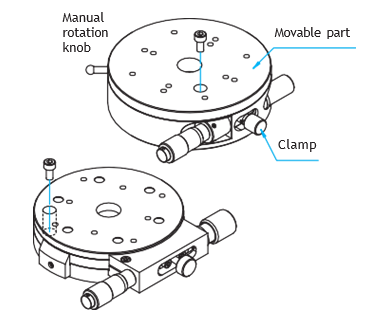
Rotation Stage
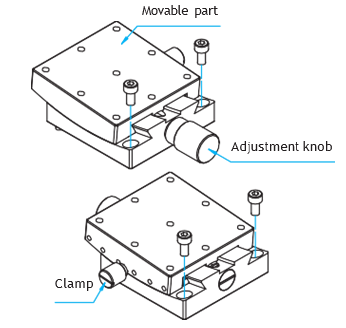
Gonio Stage
How to Read Micrometer Head and Vernier Scale
Micrometer head and vernier scale are available for reading the stage position.
How to Read a Micrometer Head
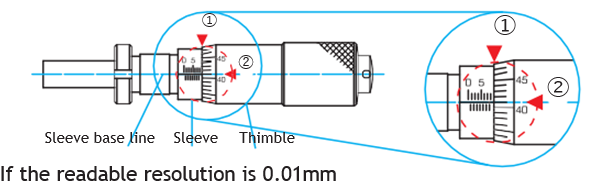
- Read the mark on the sleeve that lines up with the edge of thimble ① in units of 0.5mm. In this case, 8.5mm.
- Read the value ② on the thimble that lines up with the sleeve base line in units of 0.01mm. In this case, 0.41mm.
- Lastly, sum up 1. and 2. to confirm the current position of the manual stage. 8.5mm+0.41mm=8.91mm
How to Read a Vernier Scale
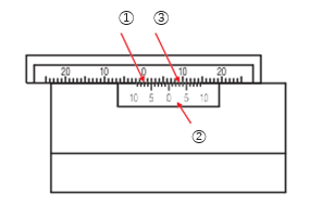
- Read the mark on scale ① that is coincident with the 0-mark on vernier scale ② in units of 1mm. In this case, 7mm.
- Read mark ① where the mark on vernier scale ② and that on scale ① line up in units of 0.1mm. In this case, 0.3mm.
- Lastly, sum up 1. and 2. to confirm the current position of the stage. 7mm+0.3mm=7.3mm
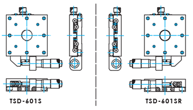
Opposite Models
When installation spaces have constraints or symmetrical systems are required, we offer opposite models without price difference. The configuration and orientation of opposite models are as follows.
For single axis
Opposite models will be axially symmetrical in the external dimensions.
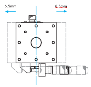
Travel
Travel is described with ±.
(E.g.) In the case of ±6.5mm, with the outline drawing position as the center, move for (+)6.5mm in one direction, and move for (-)6.5mm in the opposite direction. In this case, the full travel is 13mm.
Grease Used
We use an appropriate grease for each of our manual stages according to the respective characteristics.
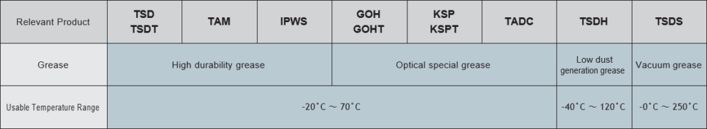
High Durability Grease
A high-grade versatile grease for industrial use. It is best suited for electric motor bearings or machine tool bearings
which are particularly required for high quality and high performance.
In addition, it is excellent in noise reduction, and can be used for a wide range of applications
Low Dust Generation Grease (AFF Grease manufactured by THK Co., Ltd.)
Best suited for use in clean rooms because of its excellent low dust generation properties. Since its viscosity resistance
is low, its rolling resistance is stable and excellent in following capability at low speed. Compared with other low dust generation greases, this grease can offer longer greasing intervals because of its excellent fretting resistance.
Vacuum Grease (Fomblin Grease YVAC2)
This grease is widely used for various vacuum equipment and for clean rooms. The grease vapor pressure is 5×10 (–13
power) Torr at 20˚C.
Optical Special Grease
This grease is used in many precision equipment fields because, in addition to lubricating properties, it has high cold
resistance and heat resistance, low oozing properties, no influence on the coating surface, and is harmless to resins.
* We can also replace the greases with ones not listed above. Contact our International Sales Division for more information.
Guide Structure
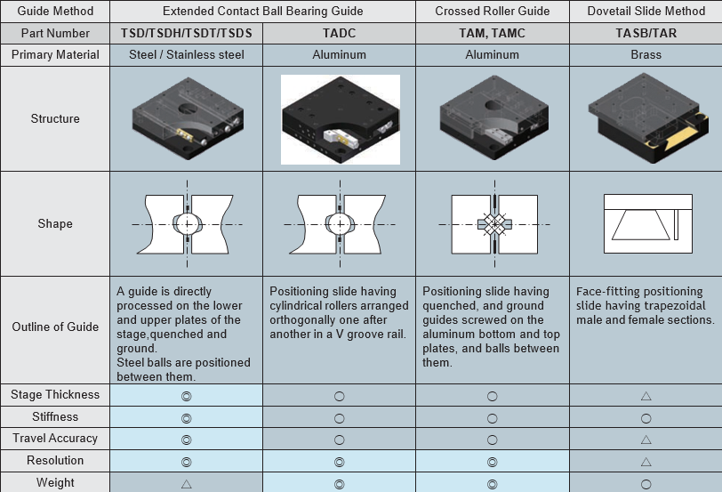
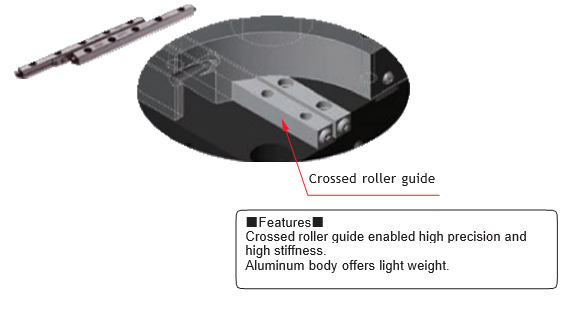
Dovetail Crossed Roller
Line contact of rollers in a V groove rail offers high stiffness. In addition, low friction and almost no differential slip are suitable for minute feeding.
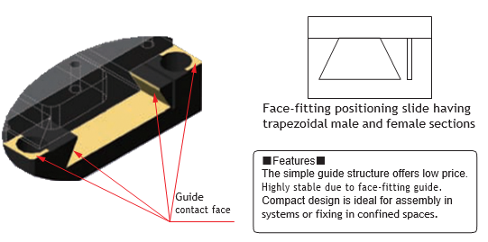
Dovetail Slide Method
The dovetail groove method with face-fitting guide mechanism is used. Its high friction coefficient is not suitable for fine positioning, but very effective in simple positioning.
Extended Contact Bearing Ball Guide (TSD/TSDH/TSDT/TSDS Series)
Feature:
- High precision
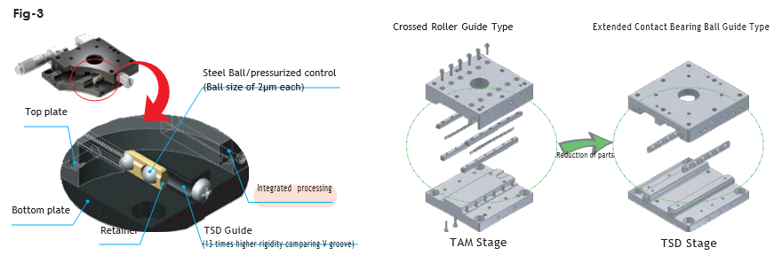
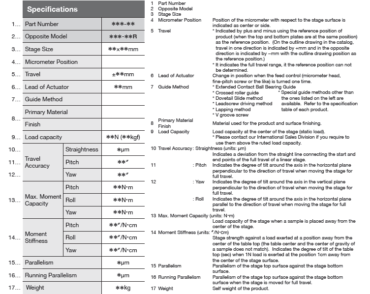
- The integral (simultaneous) machining achieves high precision (straightness: 0.7 μm or lower) As shown in Fig-3, the top and bottom plates are integrally and simultaneously machined using an originally devised machining jig to minimize respective machining errors. That is, to maintain high precision, these plates are machined in virtually the same state as when a ball is inside.
- High Load Capacity and Stiffness
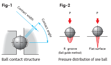
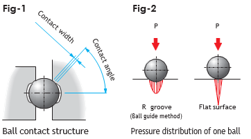
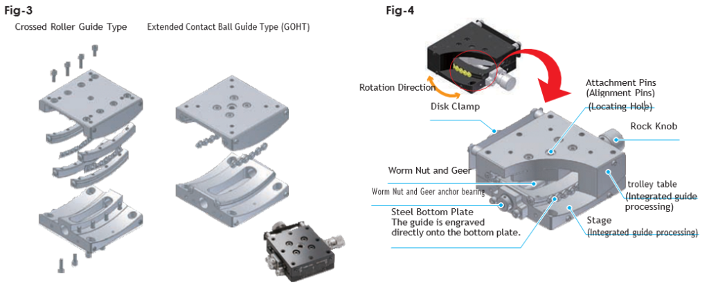
- The four-array contact structure achieves high load capacity and high stiffness (13 times stiffer then the V groove) As shown in figure 1 the ball guides are machined across the arcs so that they have R groove structure and good contact with a ball allowing stable load capacity against the load in the directions where contact with the ball occurs frequently.
- High Durability
- Long life and free of maintenance – figure 2 shows the pressure distribution of the R groove and the flat surface. As shown in the figure, pressure exerted on the R groove is dispersed and does not reach inside. Thus, metal fatigue and wear are reduced.
- Low Profile
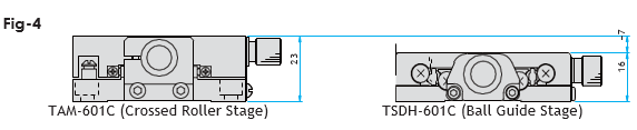
- Reduction in the number of parts enables low profiling: Fig-4 shows a comparison of thickness of a crossed roller stage and a ball guide stage. The integration of the guides into the top and bottom plates allows low profiling of the ball guide stage virtually the same state as when a ball is inside.
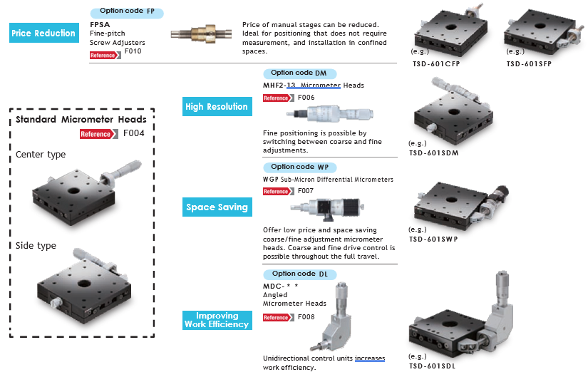
Micrometer control position / feed control
Change the micrometer control position or feed control to suit your purpoSelect according to your purpose such as for price reduction and space saving.
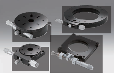
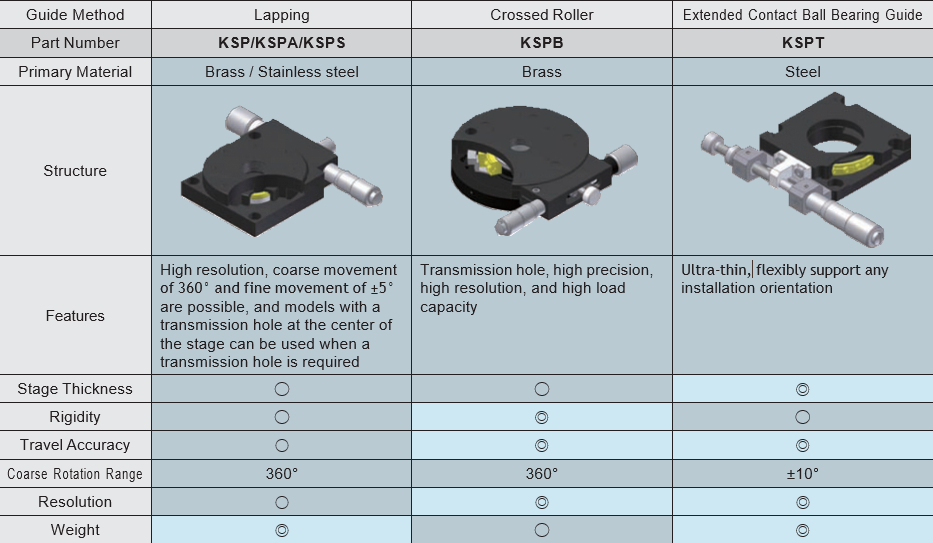
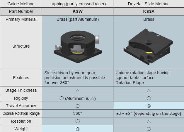
Rotation Stages Guide
Stages used for adjustment by rotating samples
Coarse/fine movement type, transmission hole type, low- profile square type and other types are available to suit your purpose.
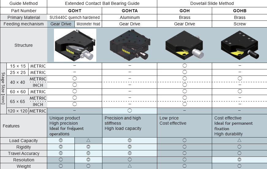
Goniometer Stages Guide
Goniometers are rotation stages that rotate about an axis that is located at a distance above the surface of the stage. Used for direction adjustment and correction, or tilting and rotation of samples. Products with different guide mechanisms or feed mechanisms are also available.
Structures and Features
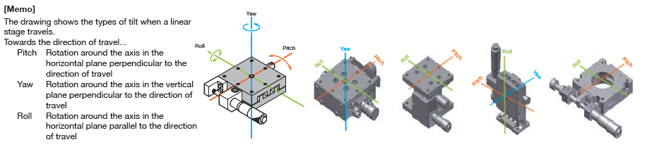
Attachment Pins (Alignment Pins)
Attachment Pins (Alignment Pins) insure that two stages that are stacked have their centers alignment, reducing assembly time.
An αβ axis stack is easily assembly by attaching an alignment pin at the top center of a GOHT series stage, and inserting it into the hole in the lower surface of the top stage. Ideal not only for assembly of single axis stages, but also for positioning when mounting on instruments or devices.
Extended Contact Ball Bearing Guide Method (GOHT/GOHTA Series)
Feature:
- High precision
- Our original processing technology achieved an integral structure of the main body and the guides. As shown in Fig-3, because the crossed roller type goniometer stage, which has been the mainstream, has the guide separate from the main body, there are many parts. Assembling a large number of parts caused errors or variation, resulting in translation errors, that is, deviation in the most important rotation center when the stage moved. Our goniometer stage as shown in Fig-4, has the guide integrated into the main body in order to compensate for assembly errors or variation by machining accuracy. With the integral structure, the displacement of the rotation center is reduced.
- High Load Capacity and Stiffness
- The four-array contact structure achieves high load capacity and high stiffness (13 times stiffer then the V groove) As shown in figure 1 the ball guides are machined across the arcs so that they have R groove structure and good contact with a ball allowing stable load capacity against the load in the directions where contact with the ball occurs frequently.
- High Durability
- Long life and free of maintenance – figure 2 shows the pressure distribution of the R groove and the flat surface. As shown in the figure, pressure exerted on the R groove is dispersed and does not reach inside. Thus, metal fatigue and wear are reduced.
Definitions of Specifications and Terminology
Definition of Terms in the Specification Table
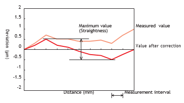
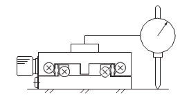
Straightness (horizontal direction)
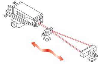
Move the stage and stop it at regular intervals throughout the full travel of the stage. At each point, measure the deviation from a reference position in the horizontal plane. The maximum deviation after correcting the deviation throughout the full travel to 0 is the straightness in the horizontal plane.
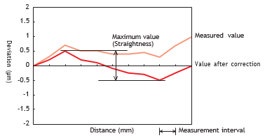
Straightness (vertical direction)
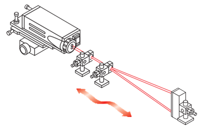
Move the stage and stop it at regular intervals throughout the full travel of the stage. At each point, measure the deviation from a reference position in the vertical plane. The maximum deviation after correcting the deviation through- out the full travel to 0 is the straightness in the vertical plane.
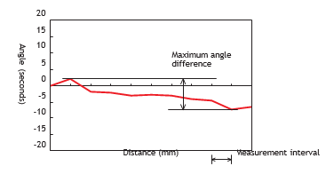
Pitch
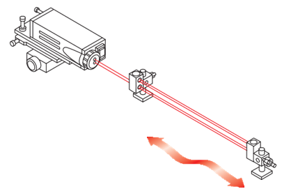
Move the stage and stop it at regular intervals throughout the full travel of the stage. At each point, measure the degree of tilt in the vertical plane. The maximum angular difference is the pitch.
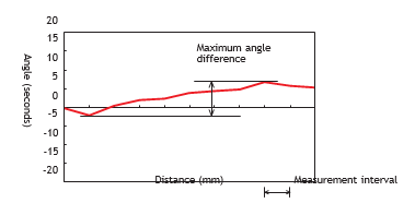
Yaw
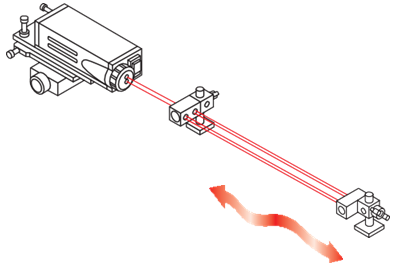
Move the stage and stop it at regular intervals throughout the full travel of the stage. At each point, measure the degree of tilt in the horizontal plane. The maximum angular difference is the yaw.
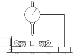
Parallelism
Fix a test indicator on an optical breadboard, bring it into contact with the top surface of the stage, and measure while moving it over the whole surface of the stage. The maximum difference of the displacement value of the test indicator is the parallelism.
Eccentricity
Fix a rotation stage on an optical breadboard. Bring a test indicator into contact with the circumference of the rotation stage, and measure while turning the stage through one full rotation of 360°. Half of the maximum difference of the displacement value of the test indicator (misalignment) is the eccentricity
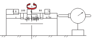
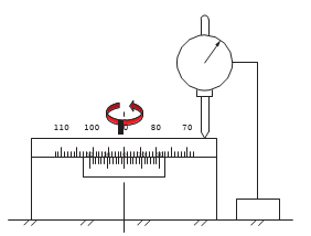
Running Parallelism
Fix a stage on an optical breadboard. Fix a test indicator on the top surface of the stage, bring it into contact with the top surface of the optical breadboard, and measure while moving the stage for the full travel. The maximum difference of the displacement value of the test indicator is the running parallelism.
Wobble
Fix a test indicator on an optical breadboard, bring it into contact with the edge of the top surface of a rotation stage, and measure while turning the stage for through one full rotation of 360°. The maximum difference of the displacement value of the test indicator is the wobble.
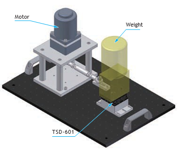
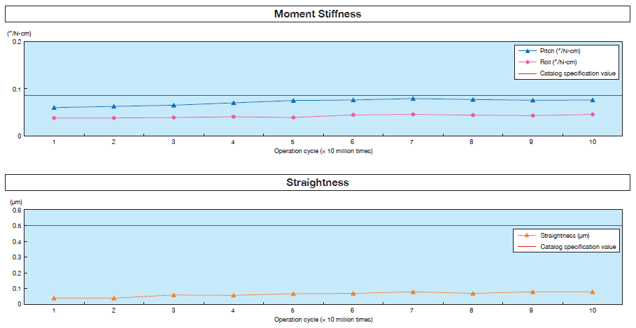
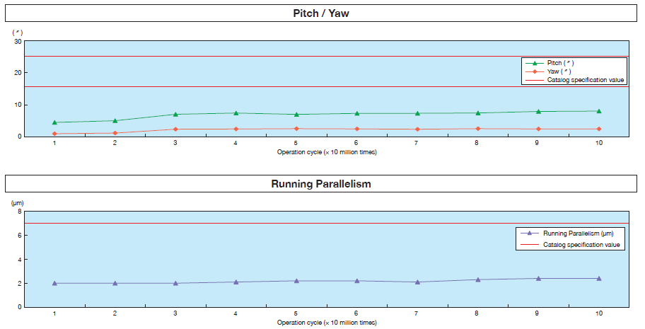
Durability Data of Manual Ball Guide Stages
Translation Stage
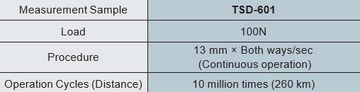
TSD series
After 10 million cycles of operation, the guide performance is stable without significant change in the stiffness, straightness, pitching, yawing, and running parallelism of the stage guide.
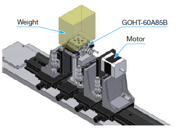
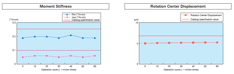
Goniometer Stage
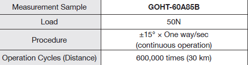
GOHT series
After 600,000 cycles of operation, the guide performance is stable without significant change in the stiffness and rotation center displacement of the stage guide.
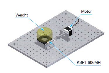
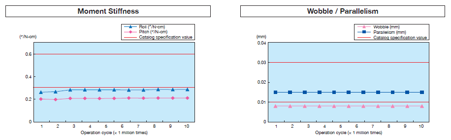
Rotation Stage
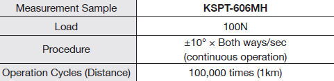
KSPT series
After 100,000 cycles of operation, the guide performance is stable without significant change in the stiffness, wobble, and parallelism of the stage guide.